Low-maintenance cogless electric generator featuring magnetic levitation

a cogless electric generator, low-maintenance technology, applied in the direction of mechanical energy handling, magnetic circuit rotating parts, magnetic circuit shape/form/construction, etc., can solve problems such as vibration in the generator, and achieve the effects of increasing the magnetic flux available, generating higher power, and increasing the magnetic flux

Inactive Publication Date: 2016-03-17
MOSKOWITZ JAY +2
View PDF14 Cites 1 Cited by
  • Summary
  • Abstract
  • Description
  • Claims
  • Application Information

AI Technical Summary

Benefits of technology

[0025]The use of both inner ring magnets and outer ring magnets increase the magnetic flux available and will generate higher power. Higher power may also be achieved at a given RPM value, by increasing the diameter of the generator (rotor and stator plates) in order to accommodate more magnets. This same power may be achievable in

Problems solved by technology

The lack of magnetic attraction makes assembly and maintenance of the rotor/stator configuration an easy process as compared to the difficult job associated with strong rotor magnets that immediately attempt to lock themselves against the metal in the stator when a attempting to disassemble a unit, and thereby require special tools and

Method used


Image

  • Low-maintenance cogless electric generator featuring magnetic levitation
  • Low-maintenance cogless electric generator featuring magnetic levitation
  • Low-maintenance cogless electric generator featuring magnetic levitation

Examples


Embodiment Construction

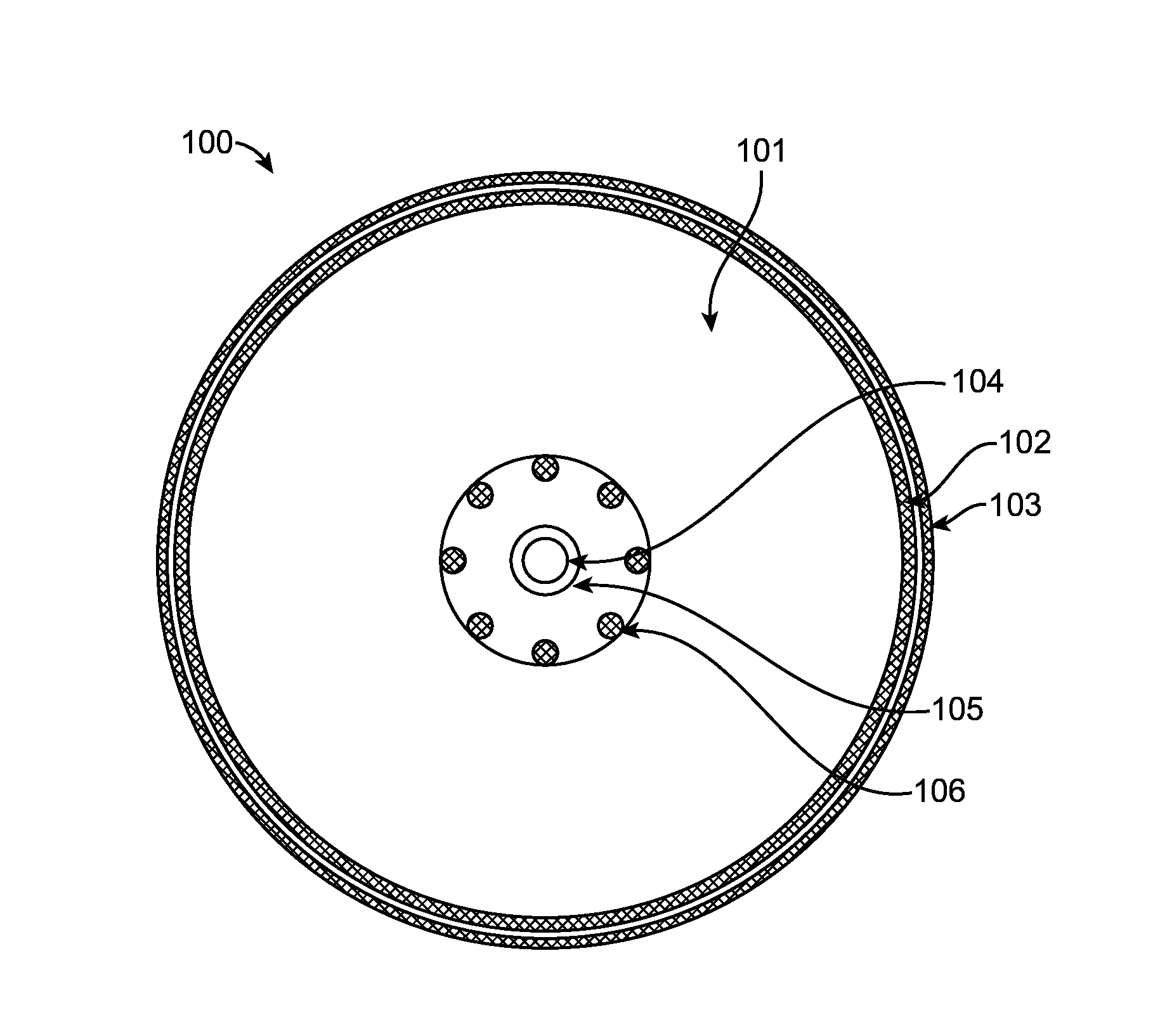
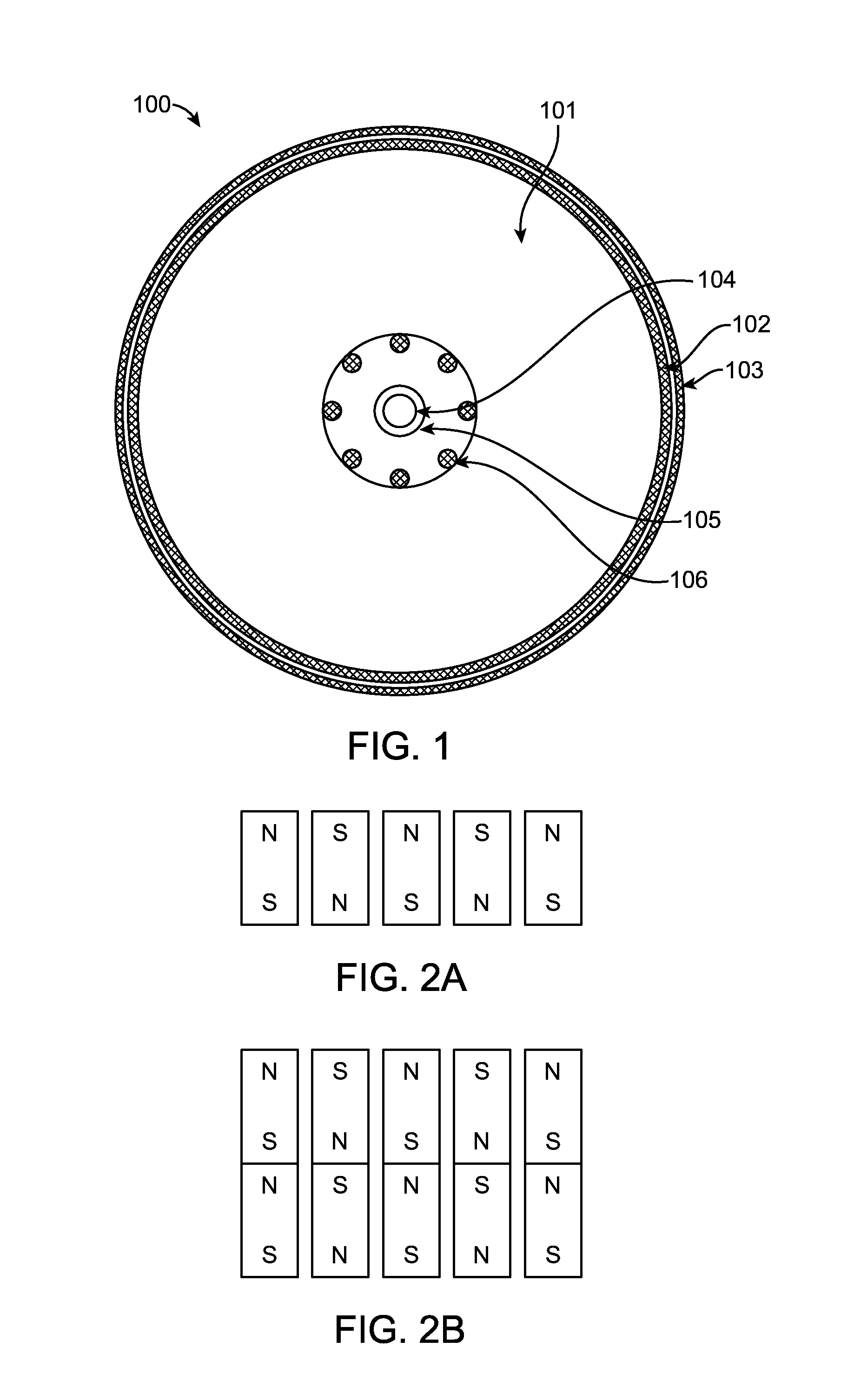
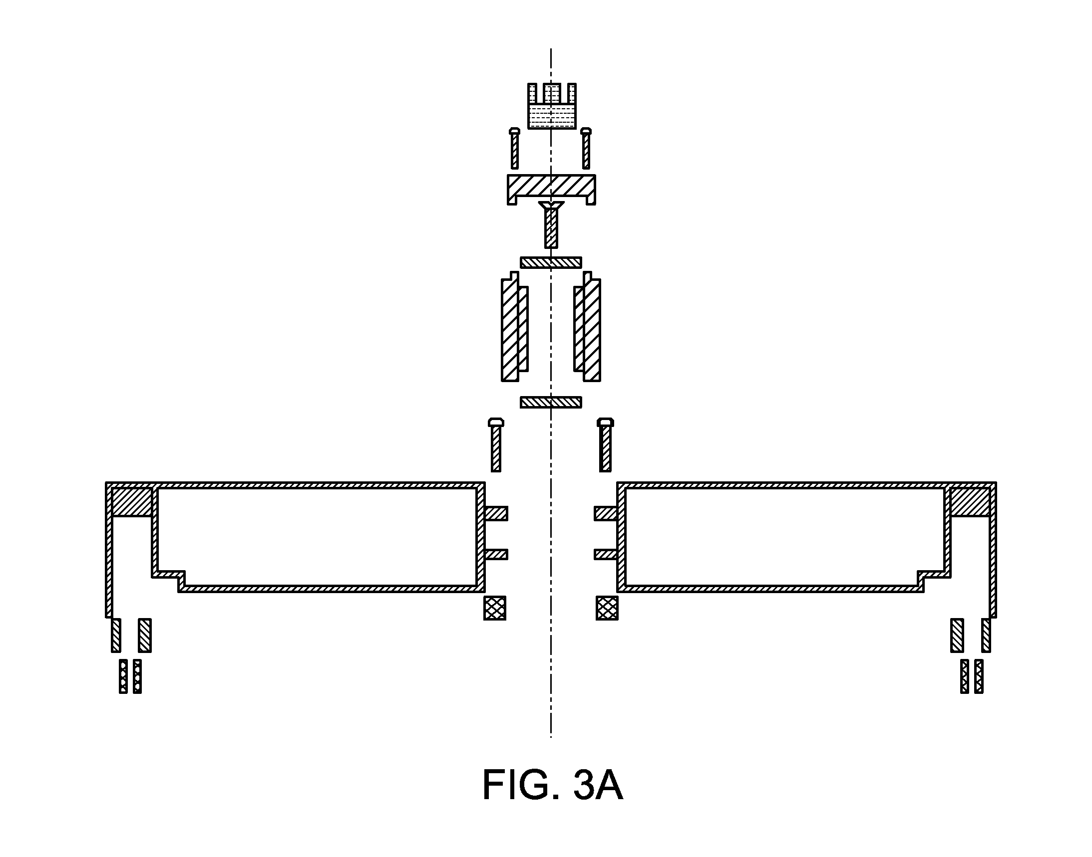
[0060]The embodiment of the present disclosure is illustrated in detail through FIGS. 1 to FIGS. 23. The generator of this invention creates electrical energy by rotating a magnetic field formed by permanent magnets, across a radial air-core set of coils. Mechanical energy, derived from wind from the movement of air masses passing over a turbine, moving of falling water, from a steam turbine, from combusting gasoline, and other forms of such kinetic and potential energy is directed to generate rotation along a shaft which is connected to a plate to form a rotor.

[0061]FIG. 1 shows a plan view of the rotor consisting of a circular base plate 101 made of aluminum, composite or other non-magnetic material. Rotational energy is applied to this rotatable element through the shaft 104 which terminates at this plate. The rotor contains a vertical outer 103 and inner 102 band separated by an air gap. This gap is formed between one set of magnets place along the outer surface of the inner ban...


PUM


Abstract

A cogless electric generator consisting of a compressed nearly all copper air core stator placed within a surrounding rotor containing a plurality of permanent magnets is described which is particularly suitable for direct-drive integration with small-wind turbines. Such turbines become capable of generating electric energy at very low wind speeds. A particular focus is in reducing maintenance and operational costs of such a device by eliminating magnetic attraction of internal components typical of such generators and by reducing friction on bearings through the use of magnetic levitation. Techniques are employed to reduce eddy currents to increase the efficiency of the generator. Air scoops and air flow considerations combined with convective elements intimately in contact with and extending through the stator, allow heat directly from the stator to be dissipated externally. When the generator is assembled and disassembled for service, there is no magnetic attraction or repulsion that would otherwise make such service difficult, dangerous or require special handling tools.

Description

[0001]This application claims the benefit of U.S. Provisional Application No. 62 / 050,935, filed Sep. 16, 2014, which is incorporated herein by reference for all purposes.[0002]This invention pertains to an electric generator consisting of a non-metallic stator and a rotor containing a plurality of permanent magnets that is capable of starting to generate electricity with the application of a minimal amount of torque to the rotor because of the elimination of magnetic attraction between elements of the stator and rotor as well as reduced friction in the turning of the rotor through the application of magnetic levitation. This non-cogging invention lends itself to the creation of large diameter generators that create greater speeds of magnets across dense stator coils at relatively low RPMs thereby generating high power levels while eliminating complex gearing systems found in large scale turbines, the energy losses inherent in them and the excessive maintenance costs associated with ...

Claims


Application Information

Patent Timeline
IPC IPC(8): H02K15/04H02K1/27H02K3/28H02K3/30H02K7/08H02K7/09H02K9/00H02K9/02H02K9/22
CPCH02K15/0435H02K3/30H02K1/27H02K3/28H02K7/09H02K9/22H02K9/02H02K9/005H02K7/08H02K21/12H02K29/03H02K3/47H02K5/1677H02K9/06H02K15/0478H02K15/12H02K11/20H02K9/227
Inventor MOSKOWITZ, JAYPERLESS, ROBERTHANSEL, STEVEN J.
Owner MOSKOWITZ JAY
Why Eureka
Try Eureka