Method of operating a pressure-retarded osmosis plant

a technology of osmosis plant and pressure retarded osmosis, which is applied in the direction of water treatment multi-stage treatment, water treatment parameter control, and membranes. it can solve the problems of increasing power consumption, limiting the operating flux of the membrane, and requiring periodic membrane cleaning-in-place procedures

Active Publication Date: 2016-03-24
I D E PROJECTS LTD
View PDF3 Cites 1 Cited by
  • Summary
  • Abstract
  • Description
  • Claims
  • Application Information

AI Technical Summary

Benefits of technology

[0010]According to the present invention there is provided a method of operating a pressure reduced osmosis plant, the plant comprising at least one osmosis element having a semi-permeable membrane, the semi-permeable membrane defining a feed side and a permeate side of the osmosis element, the method comprising, in a first mode of operation, supplying a feed stream having a relatively high concentration of solute to the feed side in a cross flow configuration, supplying a permeate stream having a relatively low concentration of solute to an inlet of the permeate side in a dead end filtration flow configuration, and receiving a feed outlet stream from the feed side wherein permeate has passed through the semi-

Problems solved by technology

A persistent problem with known osmosis systems is that of fouling of the semi-permeable membrane.
Membrane fouling is a global issue, which limits the membrane operating flux, increases power consumption and requires periodical membrane cleaning-in-place (CIP) procedures.
This may result in low effectiveness and high cost, and adds environmental issues related to the CIP chemical solutions disposal.
Chemical cleaning is used more widely, however it has huge disadvantages due to system down time which stops production, high costs, environmental issues related to waste chemical disposal and it reduces membrane life time.
Both concentrative and dilutive ECP phenomena reduce the effective, net, osmotic driving force.
The effect of ICP is detrimental and it reduces the effective, net, driving force between the two solutions.
The flow configuration of the membrane process may also affect the fouling process.
The main disa

Method used


Image

  • Method of operating a pressure-retarded osmosis plant
  • Method of operating a pressure-retarded osmosis plant
  • Method of operating a pressure-retarded osmosis plant

Examples


Embodiment Construction

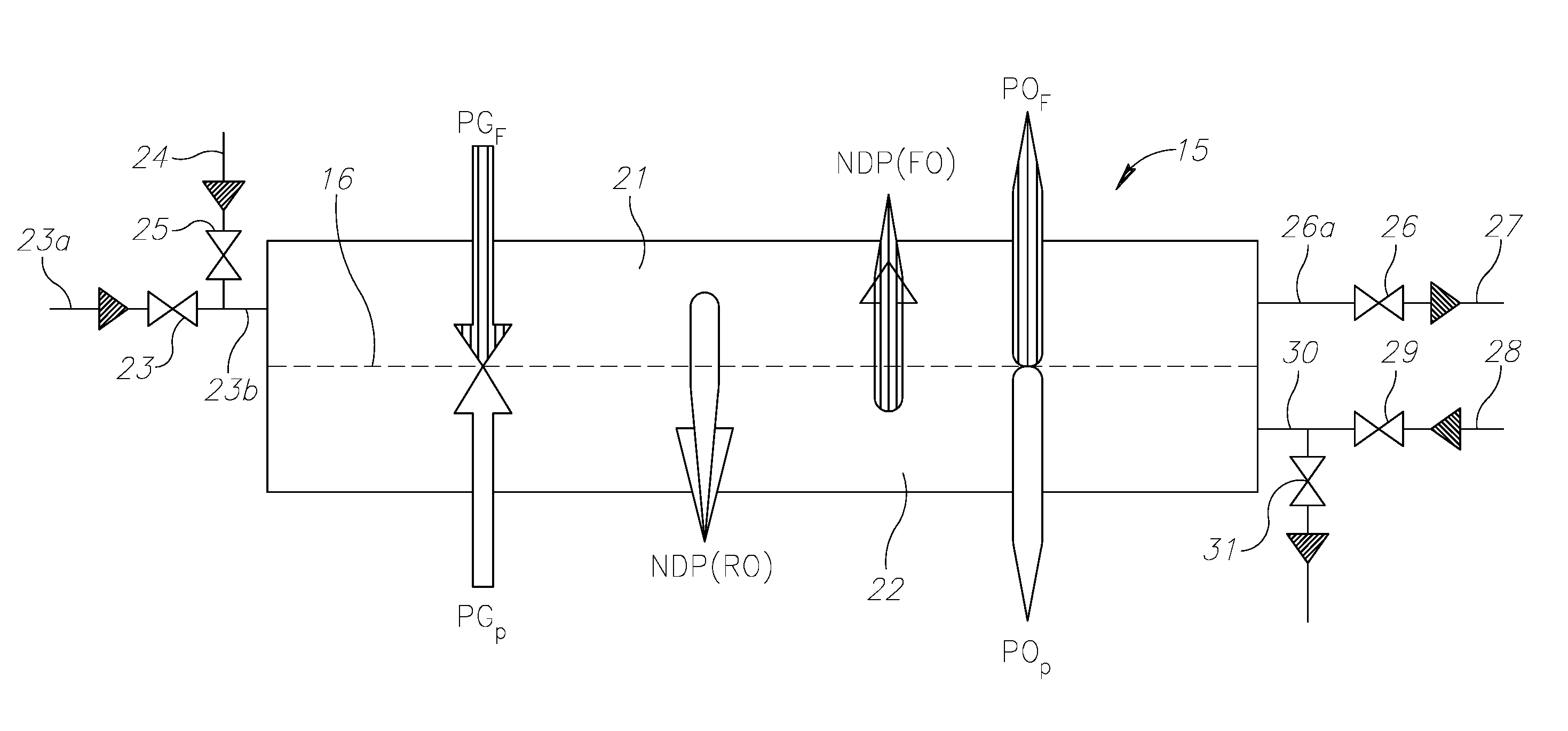
[0037]With specific reference now to the drawings in detail, it is stressed that the particulars shown are by way of example and for purposes of illustrative discussion of the preferred embodiments of the present invention only, and are presented in the cause of providing what is believed to be the most useful and readily understood description of the principles and conceptual aspects of the invention. In this regard, no attempt is made to show structural details of the invention in more detail than is necessary for a fundamental understanding of the invention, the description taken with the drawings making apparent to those skilled in the art how the several forms of the invention may be embodied in practice.

[0038]Before explaining at least one embodiment of the invention in detail, it is to be understood that the invention is not limited in its application to the details of construction and the arrangement of the components set forth in the following description or illustrated n t...


PUM


Abstract

A method of operating a pressure-retarded osmosis plant, the plant comprising at least one osmosis element having a semi-permeable membrane, the semi-permeable membrane defining a feed side and a permeate side of the osmosis element, the method comprising, in a first mode of operation, supplying a feed stream having a relatively high concentration of solute to the feed side, supplying a permeate stream having a relatively low concentration of solute to an inlet of the permeate side, and receiving a feed outlet stream from the feed side wherein permeate has passed through the semi-permeable membrane from the permeate side to the feed side, in a second mode of operation, supplying a backwash stream having a relatively low concentration to the feed side of the osmosis element such that water passes through the semi-permeable membrane, and receiving a permeate outlet stream from an outlet of the permeate side, the method further comprising alternately performing the first mode of operation, to perform a production step, and performing the second mode of operation, to reduce fouling of the semi-permeable membrane.

Description

FIELD OF THE INVENTION[0001]This invention relates to a method of operating a pressure-retarded osmosis plant, particularly but not exclusively for use in power generation.BACKGROUND OF THE INVENTION[0002]Osmosis is a known phenomenon in which water moves across a semi-permeable membrane between solutions with lesser and greater concentrations. In forward osmosis (‘FO’), where the hydraulic pressure difference of the solutions is zero, the water moves from the lower concentration solution to the higher concentration solution. In pressure-retarded osmosis (‘PRO’), where hydraulic pressure is applied to the higher concentration solution in an amount which is greater than zero and lower than the osmotic pressure difference of the solutions, the rate of flux of water can be reduced. If sufficient pressure is applied to the higher concentration side, which is greater than the osmotic pressure differences of the solutions, osmotic water flow can be reversed, referred to as reverse osmosis...

Claims


Application Information

Patent Timeline
IPC IPC(8): C02F1/44
CPCC02F1/441C02F1/445C02F2303/16C02F2303/10C02F2103/08B01D61/002B01D65/02B01D2315/20B01D2321/04B01D2321/2083B01D2321/40C02F2209/005C02F2209/44C02F2301/08B01D2313/24B01D2317/04B01D2319/02Y02W10/30Y02E10/30B01D61/00B01D63/10B01D63/12B01D2315/08B01D2315/10B01D2317/00B01D2315/18B01D2317/06B01D2321/06B01D2321/20Y02A20/131Y02E10/20B01D61/0021B01D61/0024
Inventor LIBERMAN, BORIS
Owner I D E PROJECTS LTD
Why Eureka
Try Eureka