Tunable Envelope Tracking

Inactive Publication Date: 2016-03-24
QUALCOMM INC
View PDF3 Cites 8 Cited by
  • Summary
  • Abstract
  • Description
  • Claims
  • Application Information

AI Technical Summary

Benefits of technology

[0017]A resonant power converter can eliminate the largest part of these switching losses by operating in ZVS. In order for the power converter to operate in ZVS, a resonant network guarantees that the voltage at the drain terminal of the main switching transistor is null when the switching occurs. If the voltage at the drain terminal of the transistor is zero when the transistor is turning on, for example, the product of voltage across the switch and current in the switch is null. The a

Problems solved by technology

The largest contribution to low efficiency in a switching power converter is due to the switching losses and in particular to the product of voltage across the switches and current in the switches during the switching transitions.
The switching transition time is generally

Method used


Image

  • Tunable Envelope Tracking
  • Tunable Envelope Tracking
  • Tunable Envelope Tracking

Examples


Embodiment Construction
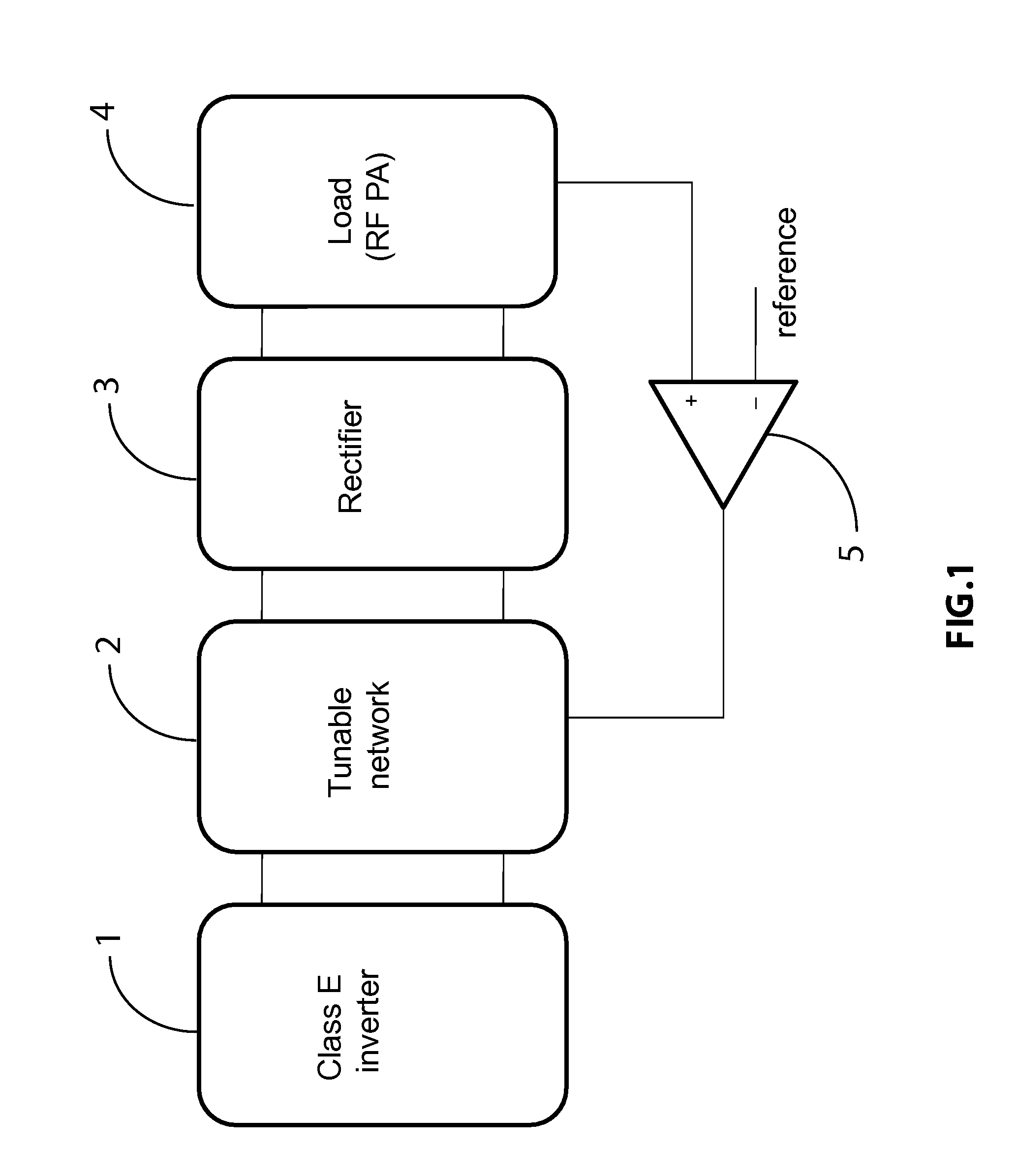
[0037]A FIG. 1

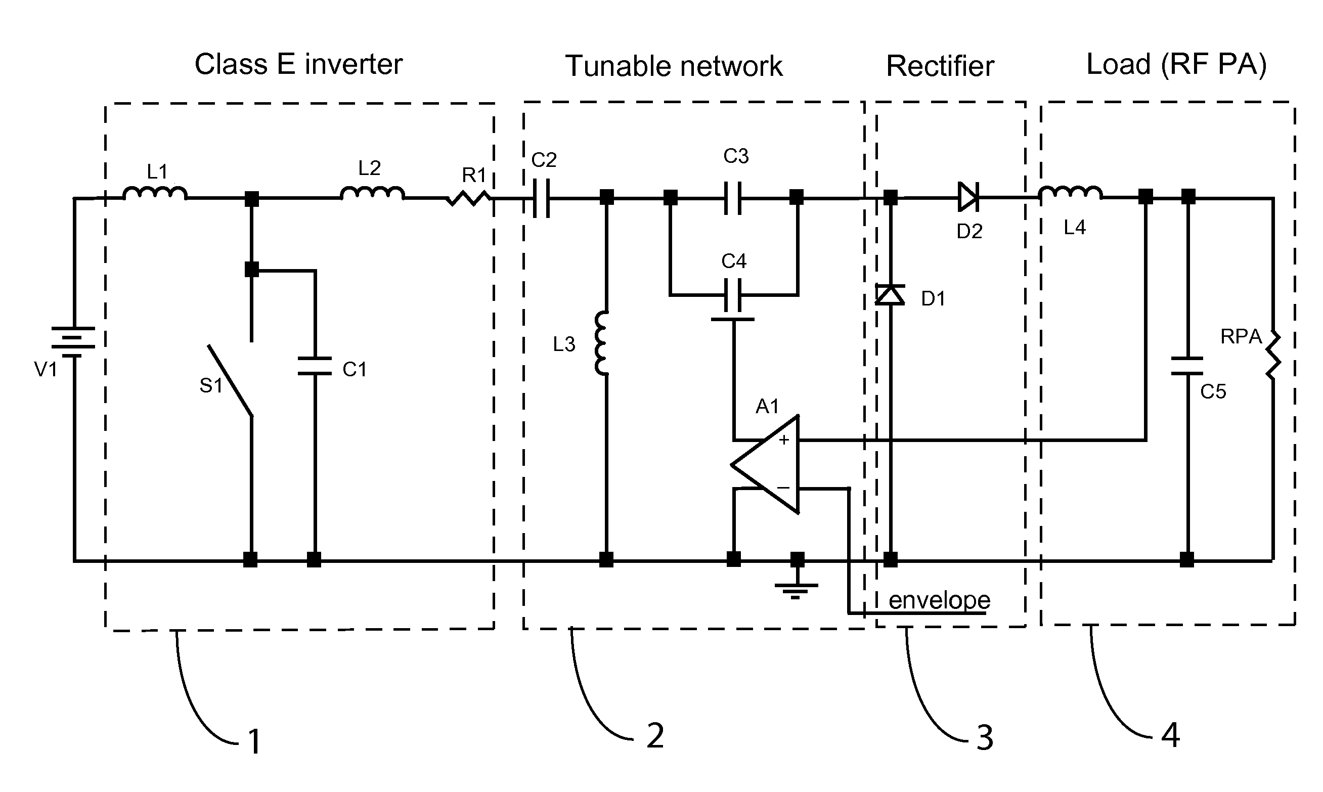
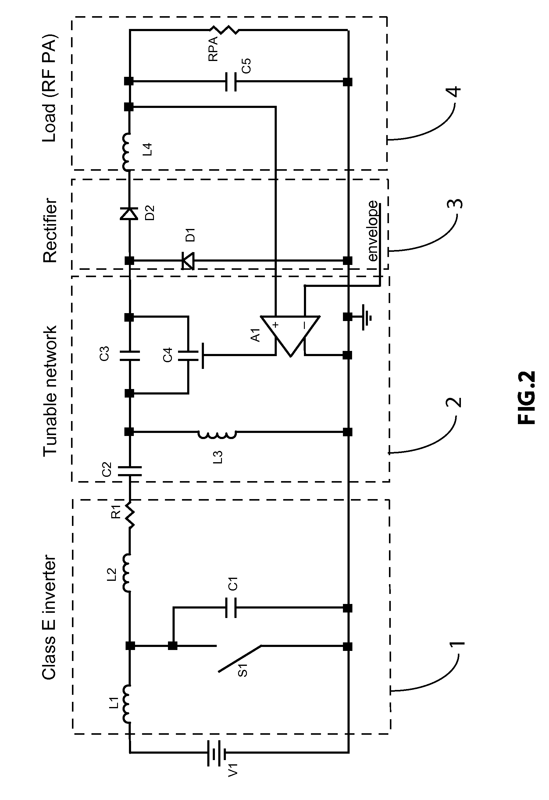
[0038]FIG. 1 shows a general block diagram of the implementation of the presented resonant envelope tracking system according to one embodiment of the present invention. The system, which could also represent a general resonant switching power converter, converts the DC signal to an AC signal, operates the control of the output power (output voltage or output current) and reconverts the AC signal back to DC, or to lower frequency AC signal, to be applied to the load. The control is adaptive depending on the input voltage, load and reference signal.

[0039]The first block 1 is represented by a DC to AC power converter, also known as inverter, and one of the most conventional configurations is the one of a class E amplifier. The class E amplifier is a resonant amplifier generally comprising a switching element and a resonant network. The switching element is commonly a high frequency FET transistor with its source coupled to a ground terminal. The resonant network coupled ...


PUM


Abstract

A novel method to provide power management to a radio frequency amplifier is described. The method makes use of a DC-AC resonant switching power converter, a resonant tunable network and a rectifier to track the envelope signal of a radio amplifier system. This system provides a fast, efficient and clean supply to the radio frequency amplifier. The resonant power converter may be implemented with a class E inverter. The resonant power converter may be operated efficiently by switching at zero voltage switching or zero current switching. By operating the resonant switching power converter at the same frequency of the radio frequency amplifier, the spectrum of the power converter is immune from undesired harmonics while meeting the bandwidth requirement. By adaptively tuning the tunable resonant network, the output voltage of the rectifier is controlled to track the envelope signal.

Description

[0001]The present application is a continuation in part of the regular patent application U.S. Ser. No. 14 / 664,878 entitled “Multiple Control Transcap Variable Capacitor”, filed by the same applicants on Mar. 22, 2015. Patent application U.S. Ser. No. 14 / 664,878US is a continuation in part of the regular patent application Ser. No. 14 / 456,184 entitled “Three Terminal Variable Capacitor”, filed by the same applicants on Aug. 11, 2014. Patent application U.S. Pat. No. 14 / 664,878 claims priority also from U.S. Provisional Patent Application U.S. 61 / 974,951 entitled “Variable Capacitor Circuit Applications”, filed by the same applicants on Apr. 3, 2014. Patent Application U.S. Ser. No. 14 / 456,184 is a continuation in part of the regular patent application U.S. Ser. No. 13 / 888,368 entitled “Analog Transcap Device” (now patent U.S. Pat. No. 8,803,288), filed by the same applicants on May. 7, 2013. Patent application U.S. Ser. No. 13 / 888,368 is a continuation in part of the regular patent ...

Claims


Application Information

Patent Timeline
IPC IPC(8): H03F3/19H03F1/02H03F3/21
CPCH03F1/0227H03F3/19H03F2200/451H03F2200/102H03F3/21H01G7/06H01L29/7391H01L29/93H01L29/94
Inventor MENEGOLI, PAOLOMARINO, FABIO, ALESSIO
Owner QUALCOMM INC
Why Eureka
Try Eureka