Member for electrophotography, image heating apparatus, image forming apparatus, and method for manufacturing member for electrophotography

a manufacturing method and electrophotography technology, applied in the field of electrophotography members, can solve the problems of degrading the fixing performance reducing the thickness of the release layer, and degrading so as to improve the thermal conductive properties of the fixing member, improve the printing speed, and save the energy of the image forming apparatus.

Active Publication Date: 2016-03-31
CANON KK
View PDF2 Cites 7 Cited by
  • Summary
  • Abstract
  • Description
  • Claims
  • Application Information

AI Technical Summary

Benefits of technology

[0008]In recent years, in order to respond to the needs of increased printing speeds and energy saving for im...

Problems solved by technology

However, the release layers are likely to suffer from abrasion due to rubbing against recording media (for example, paper), and thus required to have a certain layer thickness, and there are limitations to the reduction in layer thickness for t...

Method used


Image

  • Member for electrophotography, image heating apparatus, image forming apparatus, and method for manufacturing member for electrophotography
  • Member for electrophotography, image heating apparatus, image forming apparatus, and method for manufacturing member for electrophotography
  • Member for electrophotography, image heating apparatus, image forming apparatus, and method for manufacturing member for electrophotography

Examples


example 1-1

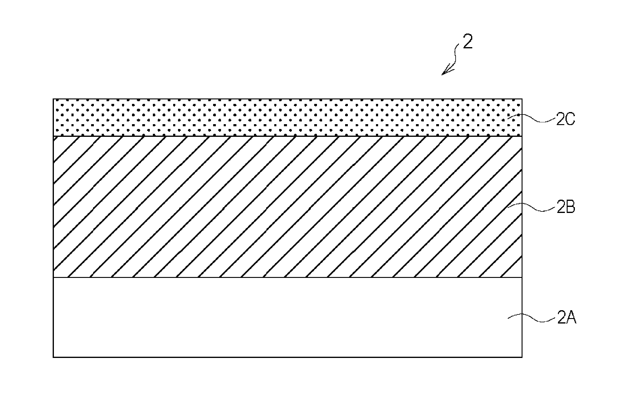
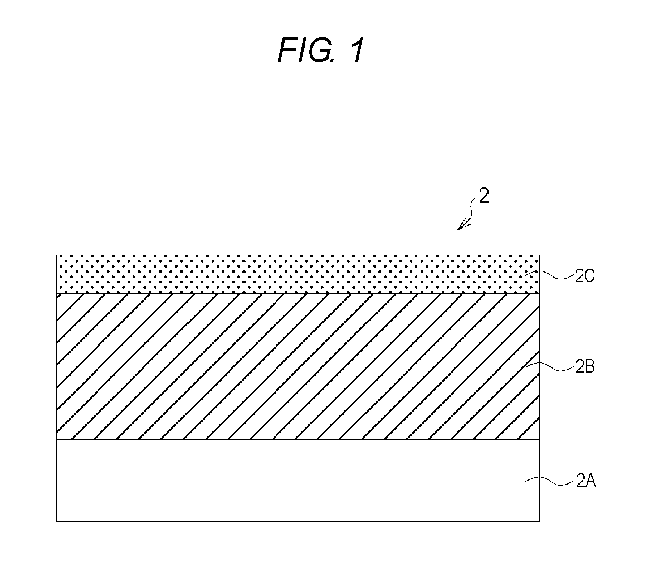
[0134](10-1) Step of Forming Elastic Layer 2B of Fixing Film

[0135]A metal belt of SUS of 240 mm in length, 40 μm in thickness, and 30 mm in outside diameter (flexible endless belt member) was used as the substrate 2A. For a region of 230 mm in length excluding both ends of 5 mm on the outer peripheral surface, a rubber-based primer (Trade Name: X-33-174A / B, from Shin-Etsu Silicone Co., Ltd.) was used and applied onto the substrate 2A to apply a primer layer in a thin and uniform fashion. Then, this was put in an electrical oven, and dried for 30 minutes at 200° C. In addition, for a material of the elastic layer 2B, a well-known addition-curable liquid silicone rubber having a methyl group in a side chain (Trade Name: “KE-1281-A / B”, from Shin-Etsu Silicone Co., Ltd.) was used, in which metal silicon filler of approximately 6.0 μm in average particle size in a fracture geometry (Trade Name: M-Si #600, from KINSEI MATEC CO., LTD.) was mixed as a thermal conductive filler. Specifically...

examples 1-2 , 1-3

Examples 1-2, 1-3

[0151]In the same way as in Example 1-1 except that the integrated amount of light from the ultraviolet light was adjusted to the values listed in Table 1, the fixing films 2 according to Examples 1-2 and 1-3 were each prepared, and subjected to the evaluation. The evaluation result is shown in Table 1. Also in the present examples, in regard to adhesion, the failure mode was a cohesive failure in the elastic layer 2B.

example 2-1

[0152]In the same way as in Example 1 except that a low pressure mercury UV lamp with a center wavelength of 254 nm (Trade Name: GLQ500US / 11, from TOSHIBA LIGHTING & TECHNOLOGY CORPORATION (used to be HARISON TOSHIBA LIGHTING Corporation)) was used in place of the excimer UV lamp (Trade Name: MEUT-1-500, from M. D. Excimer Inc.) as a light source in the step of bonding the elastic layer 2B and the release layer 2C, the fixing film 2 was prepared, and subjected to the evaluation. The evaluation result is shown in Table 1. Also in the present example, in the adhesion evaluation, the failure mode was a cohesive failure in the elastic layer 2B.


PUM

PropertyMeasurementUnit
Thicknessaaaaaaaaaa
Thicknessaaaaaaaaaa
Thicknessaaaaaaaaaa

Abstract

Provided is a member for electrophotography, where an elastic layer including a silicone rubber and a release layer including a fluorine resin are bonded sufficiently without any adhesive layer interposed therebetween.
The member for electrophotography includes a substrate; an elastic layer including a silicone rubber, on the substrate; and a release layer provided in direct contact with the surface of the elastic layer, where the release layer includes a fluorine resin selected from the group consisting of PFA, FEP, PTFE, ETFE, PCTFE, ECTFE, and PVDF, and the elastic layer undergoes a cohesive failure when the release layer is peeled from the elastic layer in accordance with “Determination of peel strength of bonded assemblies. Part 1: 90 degree peel” specified by the Japanese Industrial Standards (JIS) K 6854-1:1999.

Description

CROSS-REFERENCE TO RELATED APPLICATIONS[0001]This application is a continuation of International Application No. PCT / JP2015 / 004539, filed Sep. 8, 2015, which claims the benefit of Japanese Patent Application No. 2014-201851, filed Sep. 30, 2014, and Japanese Patent Application No. 2015-171171, filed Aug. 31, 2015.BACKGROUND OF THE INVENTION[0002]1. Field of the Invention[0003]The present invention relates to a member for electrophotography, which is preferably used as a fixing member of an electrophotographic image forming apparatus (hereinafter, also referred to as an “image forming apparatus”) such as a copying machine and a printer, an image heating apparatus, an image forming apparatus, and a method for manufacturing the member for electrophotography.[0004]2. Description of the Related Art[0005]Fixing members for use in image heating apparatuses in image forming apparatuses such as copying machines, printers, and facsimile machines are typically members each including at least e...

Claims


Application Information

Patent Timeline
IPC IPC(8): G03G15/20B32B7/06B32B25/08B32B25/20B32B27/08B32B27/32B32B38/10
CPCG03G15/206B32B25/08B32B27/322B32B25/20B32B2307/748B32B7/06B32B38/10B32B2307/51B32B2307/54B32B27/08B32B15/06B32B15/08B32B27/18B32B27/281B32B27/304B32B27/34B32B37/06B32B2037/268B32B2262/106B32B2264/102B32B2307/202B32B2307/50B32B2310/0831B32B2327/18B32B2457/00B32B2559/00G03G15/2057
Inventor MATSUMOTO, MAMOOSHIMA, YOSHIHITO
Owner CANON KK
Why Eureka
Try Eureka