Thyristor Volatile Random Access Memory and Methods of Manufacture

Inactive Publication Date: 2016-03-31
SYNOPSYS INC
View PDF2 Cites 21 Cited by
  • Summary
  • Abstract
  • Description
  • Claims
  • Application Information

AI Technical Summary

Benefits of technology

[0015]Because the on thyristors dissipate power, power consumption in the array can be controlled by using parity bits to more closely balance numbers of on and off thyristor memory cells. For example two parity bits can define four states for a stored word that represent not

Problems solved by technology

All of the non-selected lines have potentials applied to them insufficient to change the state of any other thyristors.

Method used


Image

  • Thyristor Volatile Random Access Memory and Methods of Manufacture
  • Thyristor Volatile Random Access Memory and Methods of Manufacture
  • Thyristor Volatile Random Access Memory and Methods of Manufacture

Examples


Embodiment Construction

[0035]1. An Individual Memory Cell

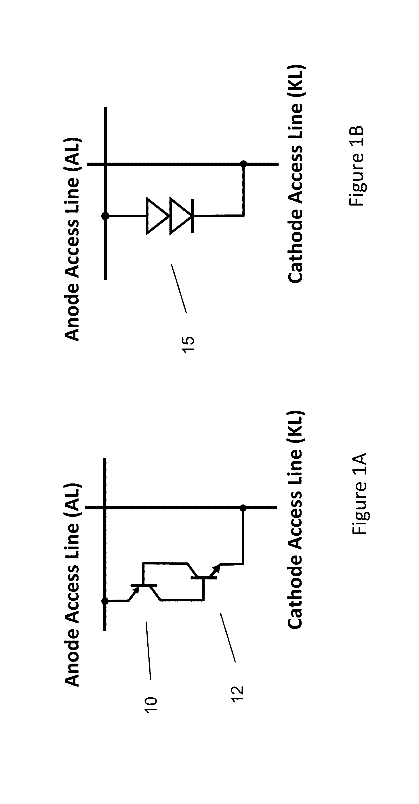
[0036]This invention provides a thyristor-based volatile memory cell, methods of manufacturing the cell, and methods of operating an array of such cells. The memory cell has particular utility for use in dynamic random access memory (DRAM) integrated circuit, as well as circuits in which DRAM memories are embedded. FIG. 1A is a circuit schematic of a thyristor coupled between an anode access line (AL) and a cathode access line (KL). The thyristor consists of two cross-coupled bipolar transistors 10 and 12. The emitter of PNP transistor 10 is coupled to the anode access line, while the emitter of NPN transistor 12 is coupled to the cathode access line. The collectors and bases of the two transistors are coupled together as shown. FIG. 1B is an equivalent circuit schematic showing the thyristor 15 using conventional notation. This notation is used in subsequent figures below.

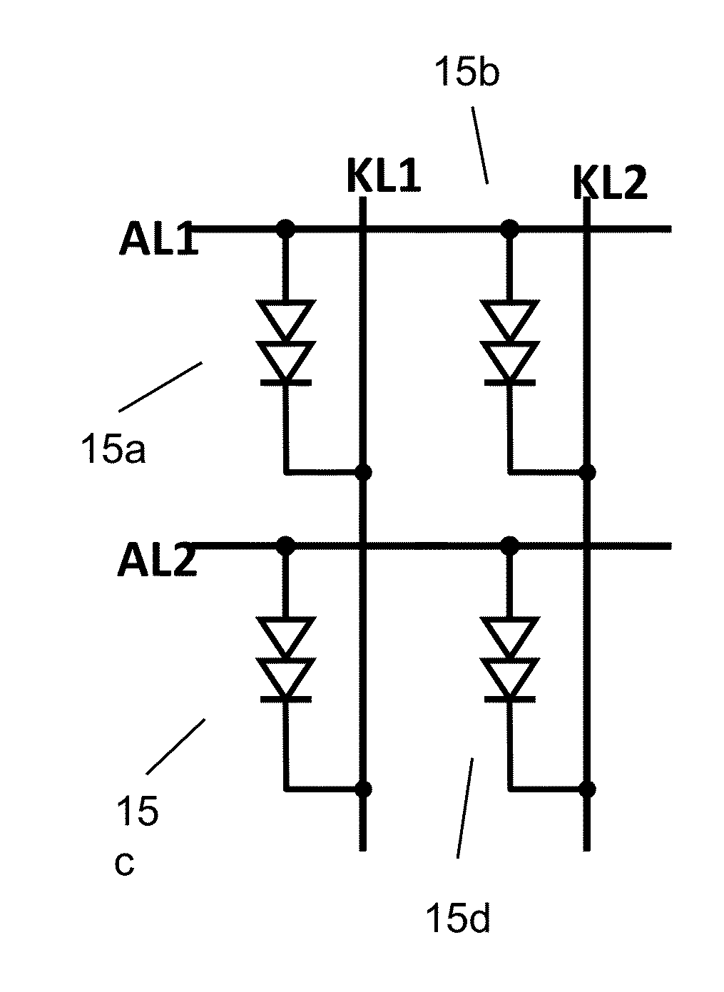
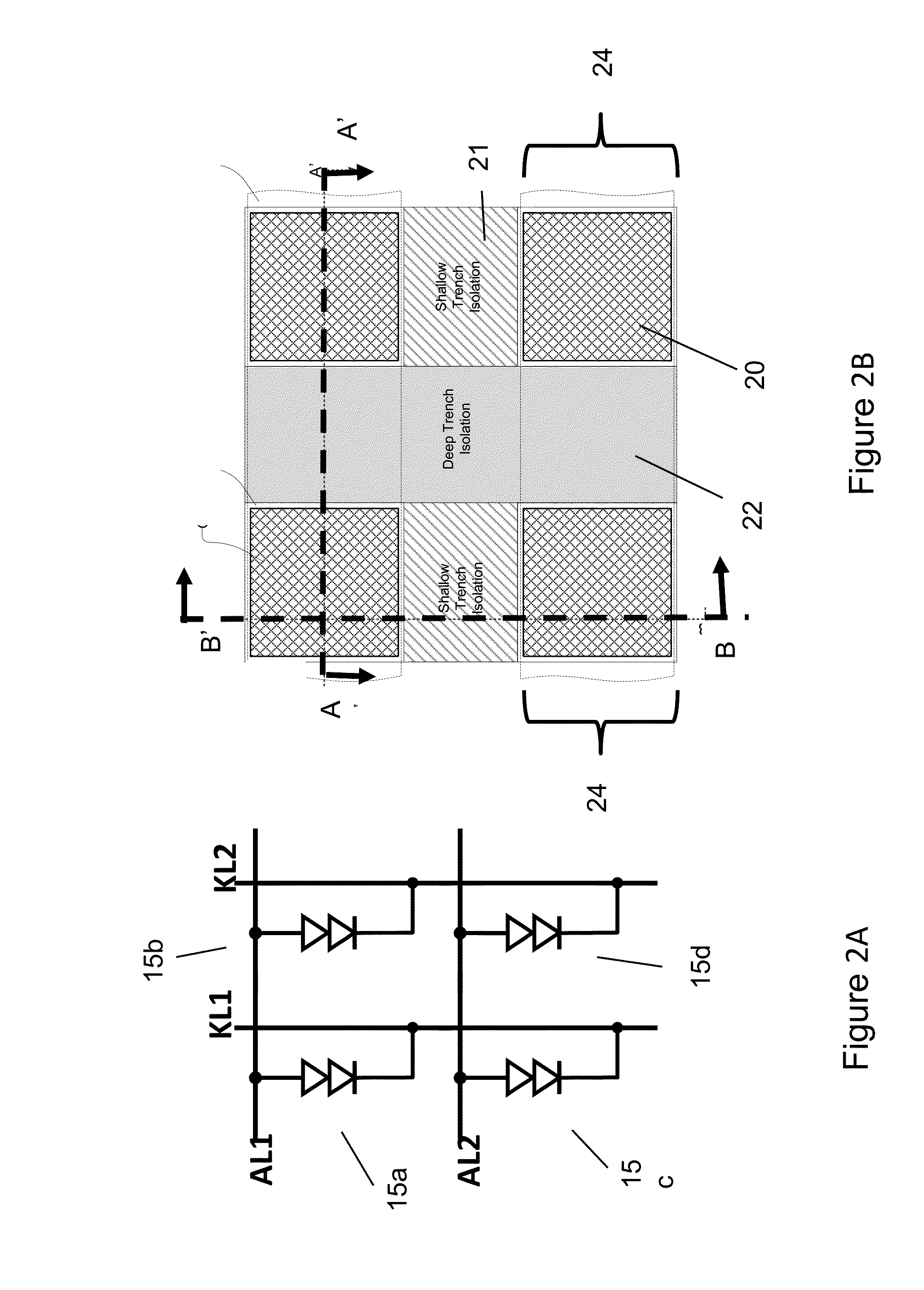
[0037]FIG. 2A illustrates an array of four thyristors 15a, 15b, 15c, and 15d ...


PUM


Abstract

A volatile memory array using vertical thyristors is disclosed together with methods of fabricating the array.

Description

CROSS-REFERENCE TO RELATED APPLICATIONS[0001]This patent application is related to U.S. patent application Ser. No. ______, filed of even date and entitled, “Methods of Reading and Writing Data in a Thyristor Random Access Memory,” U.S. patent application Ser. No. ______, filed of even date and entitled, “Methods of Retaining and Refreshing Data in a Thyristor Random Access Memory,” U.S. patent application Ser. No. ______, filed of even date and entitled, “Power Reduction in Thyristor Random Access;” all of which claim priority from U.S. Provisional Patent Application No. 62 / 186,336, filed Jun. 29, 2015 and entitled, “High-Density Volatile RAMs, Method of Operation and Manufacture Thereof,” and is a continuation-in part of U.S. application Ser. No. 14 / 590,834, filed Jan. 6, 2015 and entitled, “Cross-Coupled Thyristor SRAM Circuits and Methods of Operation,” which claims priority from U.S. Provisional Patent Application No. 62 / 055,582, filed Sep. 25, 3014; all of which are incorporat...

Claims


Application Information

Patent Timeline
IPC IPC(8): H01L27/102H01L21/3205H01L21/324H01L21/762H01L29/06H01L29/10H01L29/16H01L29/66H01L29/749
CPCH01L27/1027H01L29/749H01L29/66363H01L29/102H01L21/32053H01L29/16H01L29/0649H01L21/76224H01L21/324H01L29/1016H01L28/00H01L29/0834H01L29/4236H01L29/456H01L29/66356G11C11/39H01L21/28035H01L21/321H01L29/45
Inventor LUAN, HARRYBATEMAN, BRUCE, L.AXELRAD, VALERYCHENG, CHARLIE
Owner SYNOPSYS INC
Why Eureka
Try Eureka