Heatable capacitor and circuit arrangement

a capacitor and circuit technology, applied in the direction of variable capacitors, capacitors with temperature varied dielectrics, capacitors, etc., can solve the problems of reducing the control range of the energy transmission system to produce as efficient a transmission as possible from the system, unable to achieve further operating range of the energy transmission system, and the controller of the resonance circuit cannot balance out the detuning. , to achieve the effect of increasing the availability of the resonance system

Inactive Publication Date: 2016-03-31
SIEMENS AG
View PDF9 Cites 14 Cited by
  • Summary
  • Abstract
  • Description
  • Claims
  • Application Information

AI Technical Summary

Benefits of technology

[0023]In a particular advantageous embodiment of the method, information relating to the replacement of the capacitor is generated as a function of the calculated residual service life. This information is conveyed to a service technician or to service software, for instance. Prompt replacement of a capacitor or a capacitor module prior to its failure can increase the availability of the resonance system in which the capacitor module is deployed.

Problems solved by technology

The control range for the adjustment of the energy transmission system to produce as efficient a transmission as possible from the system, is therefore very significantly restricted.
Thus, a further operating range of the energy transmission system is not desired in most cases.
Since, in inductive charging systems, a geometric offset of the transmitter coil on the primary side) and the receiver coil on the secondary side is possible, the controller of the resonance circuit can no longer balance out the detuning if the resonance circuit has certain specifications, because normative requirements restrict the control range of the operating frequency, also referred to as the “working” frequency.
However, a mechanically adjustable capacitor cannot be easily replaced in the power electronics by a gyrator or suchlike.
In practice, a mechanically or electromechanically adjustable capacitors do not always provide a satisfactory solution, on account of their susceptibility to need repair as well as their high cost.

Method used


Image

  • Heatable capacitor and circuit arrangement
  • Heatable capacitor and circuit arrangement
  • Heatable capacitor and circuit arrangement

Examples


Embodiment Construction

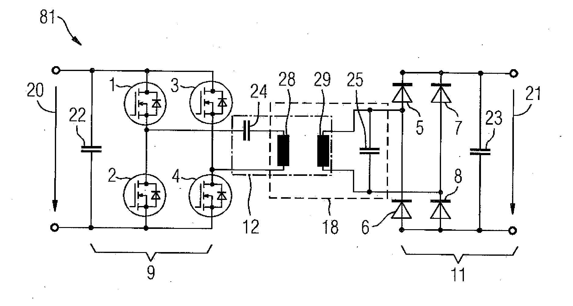
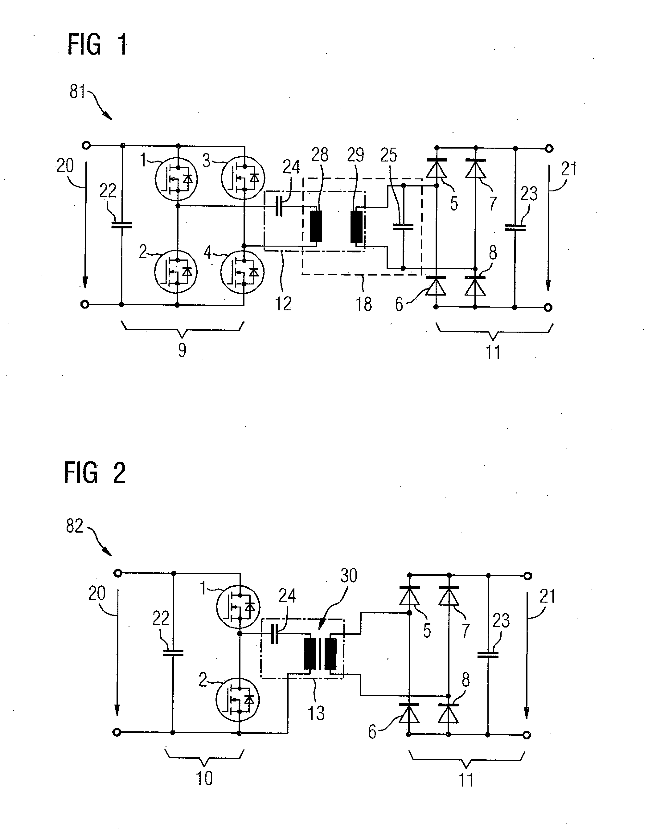
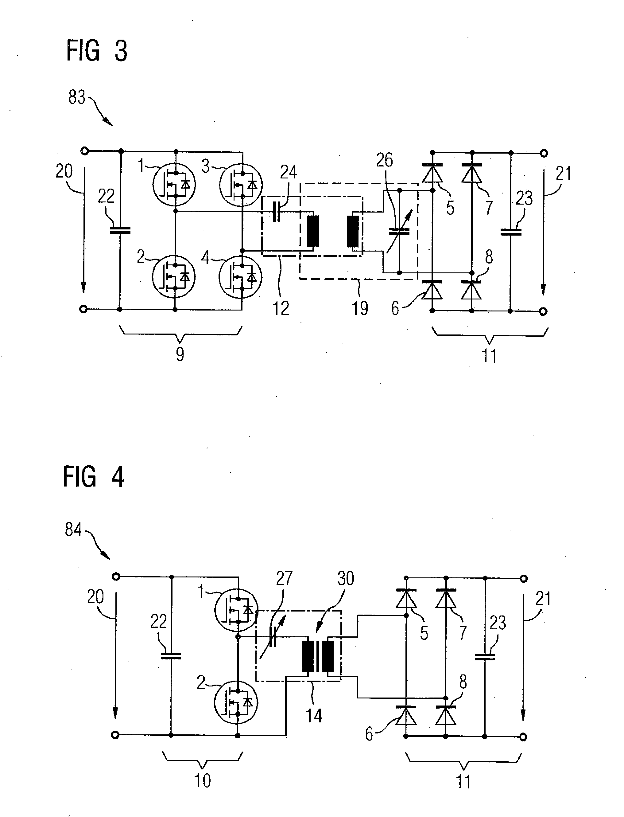
[0039]In FIG. 1, the circuit arrangement 81 is a coupled system having series or parallel circuits and couplings that provide a resonant DC converter for an inductive charging system, in particular for charging a vehicle battery, for example, having an inverter 9 and a rectifier 11. The inverter 9 has switchable power semiconductors 1, 2, 3 and 4 in a bridge circuit, and an input-side capacitance 22 across the voltage input 20. A capacitance 24 and inductance 28 are connected in series across the inverter 9 in a series circuit, thus forming a series resonant circuit 12, that is also part of the resonant circuit 18 on account of the inductive coupling of the inductance 28 with a further inductance 29 that is part of a parallel resonant circuit 18 in which that inductance 29 is parallel to a capacitance 25. The inductance 28 is also part of the resonant circuit 18, on account of the inductive coupling of the inductances 28 and 29. The parallel resonant circuit 18 is electrically conne...


PUM


Abstract

A capacitor module having a capacitor and a heater is disclosed. The temperature of the capacitor can be measured by means of a temperature sensor and the temperature of the capacitor is influenced by the heater. The capacitance value changes as a function of the temperature. Thus a circuit apparatus having a resonance converter can be tuned thereby, since the capacitance value can be regulated or controlled.

Description

CROSS-REFERENCES TO RELATED APPLICATIONS[0001]This application claims the priority of German Patent Application, Serial No. 10 2014 219 612.4, filed Sep. 26, 2014, pursuant to 35 U.S.C. 119(a)-(d), the content of which is incorporated herein by reference in its entirety as if fully set forth herein.BACKGROUND OF THE INVENTION[0002]The invention relates to a heatable capacitor and a circuit arrangement having said heatable capacitor. More particularly, in particular, the circuit arrangement relates to a resonance converter for the wireless charging of an electric vehicle and to a method for operating a resonance converter, a load resonance converter, in particular.[0003]A resonance converter is a DC converter that uses a resonant circuit and converts a DC voltage into a single-phase or multi-phase AC voltage, in particular. Resonant DC converters use an electric resonance circuit or resonant circuit having electrical reactances, capacitance and inductance, for energy transmission pur...

Claims


Application Information

Patent Timeline
Patent Type & Authority Applications(United States)
IPC IPC(8): H02J5/00H01G7/04
CPCH01G7/04H02J5/005H01G2/08H02M7/5383H02J50/12Y02T10/70H02J7/04H02J7/007192
Inventor FINKENZELLER, MICHAELMAISEL, PETERSALITERNIG, MARTIN
Owner SIEMENS AG
Why Eureka
Try Eureka