Driver device for transistors, and corresponding integrated circuit

a transistor and driver technology, applied in the direction of logic circuit coupling/interface arrangement, pulse generator, pulse technique, etc., can solve the problem of particularly compact devices, and achieve the effect of reducing propagation delay, efficient use of silicon area, and cost reduction

Active Publication Date: 2016-03-31
STMICROELECTRONICS INT NV
View PDF2 Cites 4 Cited by
  • Summary
  • Abstract
  • Description
  • Claims
  • Application Information

AI Technical Summary

Benefits of technology

[0006]A number of advantages are provided. There is a reduced propagation delay during switching-off (td-OFF) for a wide range of driving configurations, and to a large extent, irrespective of the characteristics of the external component driven. The slew rate of the output voltage is controlled. There is an efficient use of the silicon area, which leads to cost reductions. Less critical designs may be used, and the devices may be particularly compact.

Problems solved by technology

Less critical designs may be used, and the devices may be particularly compact.

Method used


Image

  • Driver device for transistors, and corresponding integrated circuit
  • Driver device for transistors, and corresponding integrated circuit
  • Driver device for transistors, and corresponding integrated circuit

Examples


Embodiment Construction

[0013]Illustrated in the ensuing description are various specific details aimed at providing an in-depth understanding of various examples of the embodiments. The embodiments may be obtained without one or more of the specific details, or with other methods, components, materials, etc. In other cases, known structures, materials, or operations are not illustrated or described in detail so that the various aspects of the embodiments will not be obscured.

[0014]Reference to an embodiment or one embodiment in the framework of the present description is intended to indicate that a particular configuration, structure, or characteristic described in relation to the embodiment is included in at least one embodiment. Hence, phrases such as in an embodiment or in one embodiment that may be present in different points of this description do not necessarily refer to the same embodiment. Furthermore, particular conformations, structures, or characteristics may be combined in any adequate way in ...


PUM


Abstract

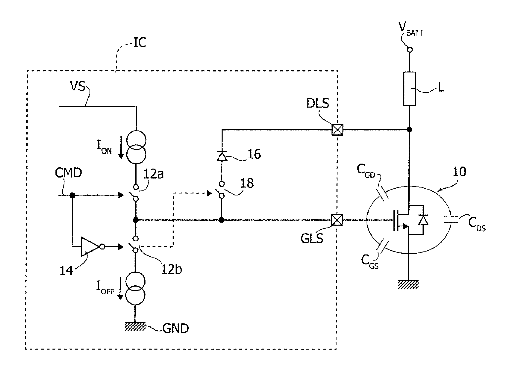
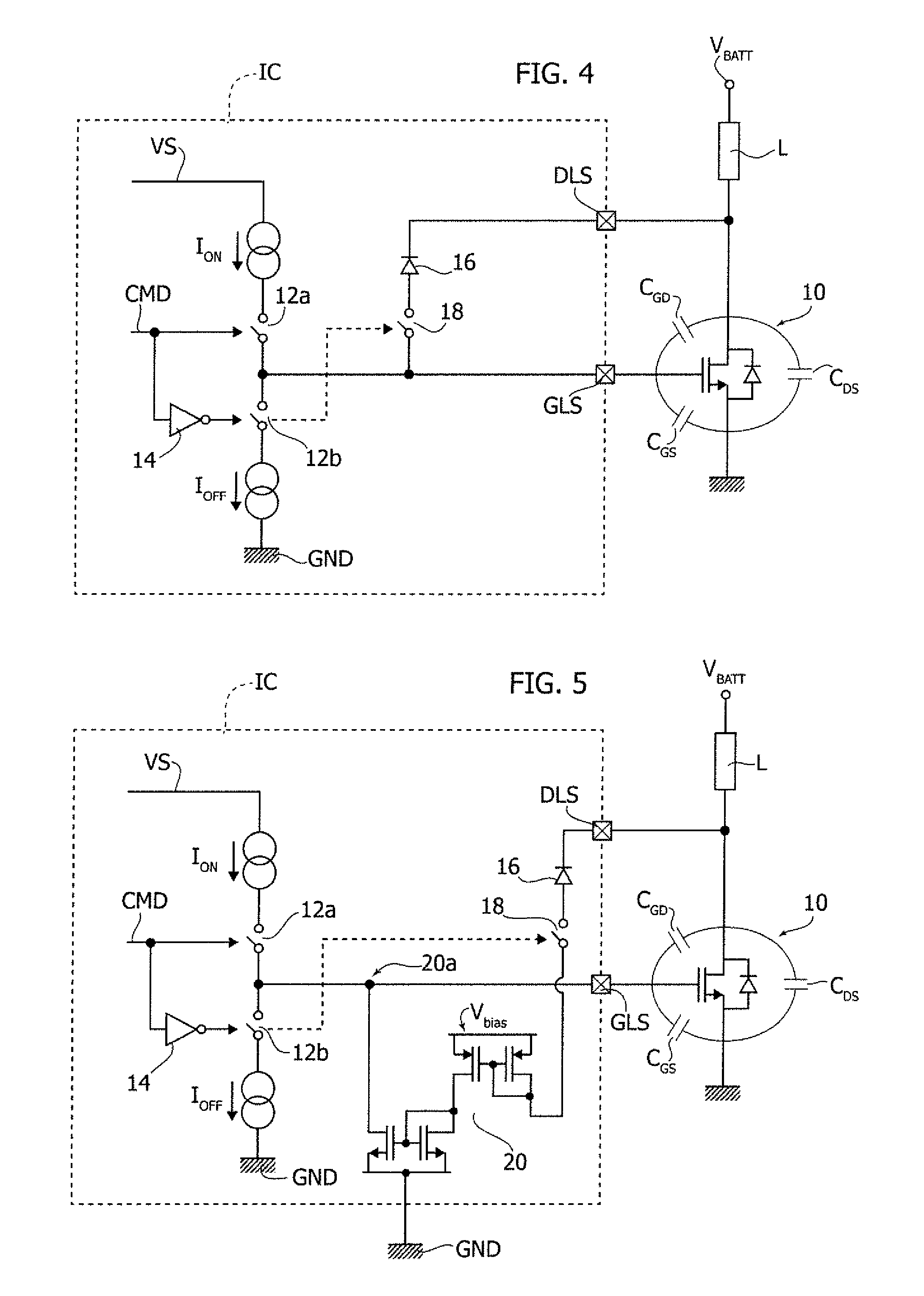
A driver device is for switching on and off a transistor for supplying a load by driving a control electrode of the transistor. The driver device includes a first terminal connected to the control electrode of the transistor, a second terminal connected between the transistor and the load, and a current-discharge path coupled to the first terminal. The current-discharge path includes a diode and is activated when the transistor is switched off. The diode becomes non-conductive to interrupt the current-discharge path when the voltage on the second terminal reaches a threshold value.

Description

FIELD OF THE INVENTION[0001]The disclosure relates to devices for driving transistors. One or more embodiments may be applied to the driving of field-effect transistors (FETs) in the vehicle sector, for example.BACKGROUND[0002]Various devices may use circuits at an integrated-circuit level for driving transistors, such as one or more FETs, for example. Various applications may drive high-power loads / actuators, for example, where the driver units cannot be completely integrated because of heat dissipation.[0003]Application of such systems may be in the vehicle sector, where systems of the type considered can carry out power-management functions, such as for actuators located in the door zone of a vehicle, for example.SUMMARY[0004]In the vehicle sector, there is a need to have straightforward and inexpensive approaches capable of providing, for example, a synthesis in terms of slew rate (SR) on the controlled load so as to limit the electromagnetic emissions, and in reducing propagati...

Claims


Application Information

Patent Timeline
Patent Type & Authority Applications(United States)
IPC IPC(8): H03K5/04H03K17/041H03K19/003
CPCH03K5/04H03K19/00323H03K17/04106H03K17/04206H03K17/166H03K19/0175
Inventor POLETTO, VANNIMILAZZO, PATRIZIALECCE, SERGIO
Owner STMICROELECTRONICS INT NV
Why Eureka
Try Eureka