Film capacitor

a film capacitor and capacitor technology, applied in the field of film capacitors, can solve the problems of capacitors that cannot withstand a high electric field, capacitor cracks on the inside of dielectric films, and capacitor leakage current increases, so as to achieve heat dissipation of film capacitors, simple configuration, and increase heat dissipation

Active Publication Date: 2016-04-07
TOYOTA JIDOSHA KK
View PDF1 Cites 5 Cited by
  • Summary
  • Abstract
  • Description
  • Claims
  • Application Information

AI Technical Summary

Benefits of technology

[0021]In the film capacitor of the above-mentioned aspect, the stacked body of the film capacitor has a simple configuration. In particular, each of the dielectric films of the stacked body includes the high thermal conductive region in which the content of the high thermal conductive filler is relatively high, and the low thermal conductive region in which the content of the high thermal conductive filler is relatively low, or the high thermal conductive filler is not contained; the high thermal conductive region is provided to continuously extend from the inside of each of the dielectric films to the end of the dielectric film, the end corresponding to the side portion other than the electrode forming ends, when seen in the thickness direction of the dielectric film; and the metalized films are stacked in the thickness direction so as to form the stacked body. In this case, a sufficient surface area of the high thermal conductive region (the high thermal conductive portion) in the surface of the stacked body can be secured, and in addition, each of the electrode forming ends is constituted by the low thermal conductive region (the low thermal conductive portion). Thus, the heat resistance and the heat dissipa

Problems solved by technology

It has also been known that, for example, in the case where large high-frequency noise, an in-rush current, a short-circuit current, or a lightning surge current flows through the capacitor during use and an operating temperature increases, a crack is produced on the inside of the dielectric film when the temperature of the capacitor returns from a high temperature to a room temperature or the like.
Accordingly, a leakage c

Method used


Image

  • Film capacitor
  • Film capacitor
  • Film capacitor

Examples


first embodiment

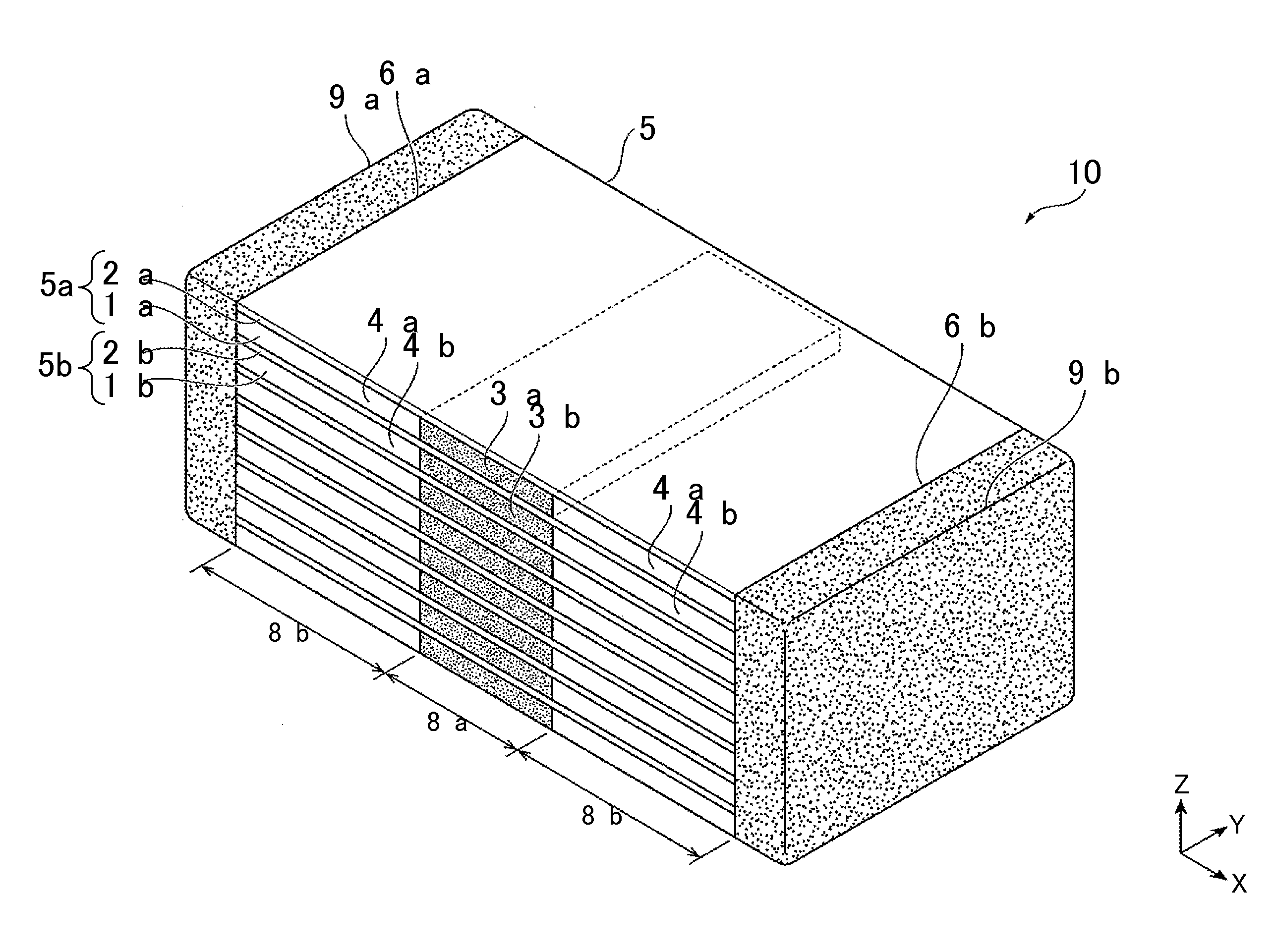
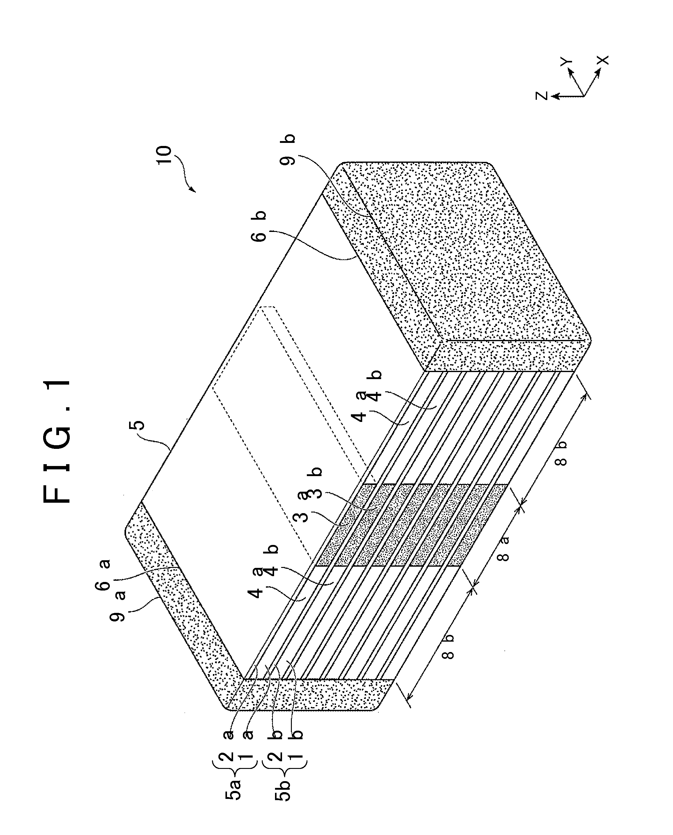
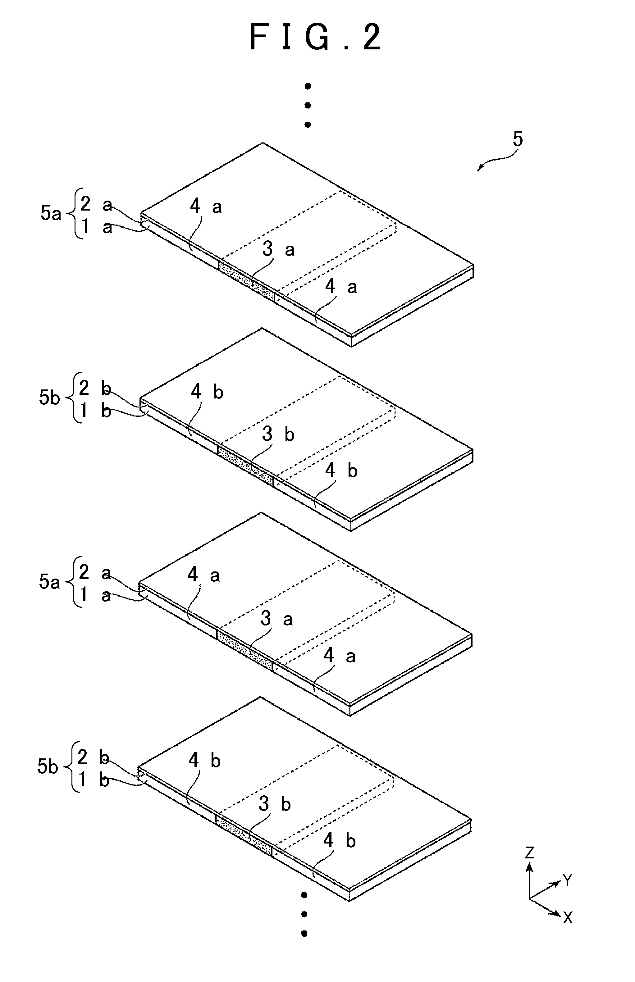
[0046]As described above, in the film capacitor 10 of the first embodiment, the stacked body 5 that is formed by stacking the metalized films 5a, 5b in the thickness direction includes: the high thermal conductive portion 8a in which the content of the high thermal conductive filler in the dielectric films la, lb is relatively high (i.e., the high thermal conductive portion 8a with the high thermal conductivity); and the low thermal conductive portions 8b in which the content of the high thermal conductive filler in the dielectric films 1a, 1b is relatively low, or the high thermal conductive filler is not contained (i.e., the low thermal conductive portions 8b with the low thermal conductivity). The high thermal conductive portion 8a is provided to continuously extend from the inside of the stacked body 5 (particularly, a center portion whose temperature may become a high temperature) to the side portions (the front and rear side portions as well as the upper and lower side portion...

second embodiment

[0048]In the second embodiment, dielectric films 1aA, 1bA of a stacked body 5A of the film capacitor 10A respectively include: high thermal conductive films 1aaA, 1baA in which the content of the high thermal conductive filler is relatively high and the high thermal conductive filler is disposed in a dispersed manner; and low thermal conductive films 1abA, 1bbA in which the content of the high thermal conductive filler is relatively low and the high thermal conductive filler is disposed in the dispersed manner, or the high thermal conductive filler is not contained.

[0049]Metal electrodes 2aA, 2bA are respectively formed on surfaces of the high thermal conductive films 1aaA, 1baA in metalized films 5aaA, 5baA. The metalized films 5aaA, 5baA are stacked in a central portion in a stacking direction (the thickness direction). The metal electrodes 2aA, 2bA are also respectively formed on surfaces of the low thermal conductive films 1abA, 1bbA in metalized films 5abA, 5bbA.

[0050]The metal...

third embodiment

[0054]In the third embodiment, dielectric films 1aB, 1bB of a stacked body 5B of the film capacitor 10B respectively include high thermal conductive films 1aaB, 1baB and low thermal conductive films 1abB, 1bbB. The high thermal conductive films 1aaB, 1baB respectively include: high thermal conductive regions 3aB, 3bB in which the content of the high thermal conductive filler is relatively high; and low thermal conductive regions 4aB, 4bB in which the content of the high thermal conductive filler is relatively low, or the high thermal conductive filler is not contained. In the low thermal conductive films 1abB, 1bbB, the content of the high thermal conductive filler is relatively low and the high thermal conductive filler is disposed in the dispersed manner, or the high thermal conductive filler is not contained.

[0055]As in the high thermal conductive regions 3a, 3b and the low thermal conductive regions 4a, 4b of the film capacitor 10 of the first embodiment, the high thermal conduc...


PUM


Abstract

A film capacitor includes a stacked body formed by stacking metalized films in each of which a metal electrode is formed on a surface of a dielectric film, at least one of the dielectric films containing a high thermal conductive filler; and external electrodes formed at electrode forming ends provided at opposed positions in the stacked body. The stacked body includes a high thermal conductive portion in which a content of the high thermal conductive filler in the at least one dielectric film is relatively high, and a low thermal conductive portion in which the content of the high thermal conductive filler in the at least one dielectric film is relatively low, or the high thermal conductive filler is not contained. The high thermal conductive portion is provided to continuously extend from an inside of the stacked body to a side portion other than the electrode forming ends.

Description

INCORPORATION BY REFERENCE[0001]The disclosure of Japanese Patent Application No. 2014-205514 filed on Oct. 6, 2014 including the specification, drawings and abstract is incorporated herein by reference in its entirety.BACKGROUND OF THE INVENTION[0002]1. Field of the Invention[0003]The invention relates to a film capacitor and in particular to a film capacitor with excellent heat resistance, heat dissipation, and workability.[0004]2. Description of Related Art[0005]Conventionally, due to an electrical characteristic of a high withstand voltage and low loss, a metalized film capacitor (also referred to as a metal-deposited-electrode type capacitor) in which metal such as aluminum is deposited on a surface of a dielectric film made of polypropylene or the like has been used in various industrial fields including a home appliance industry and an automotive industry.[0006]It has been known that an electrostatic capacitance of this type of the film capacitor greatly depends on a temperat...

Claims


Application Information

Patent Timeline
IPC IPC(8): H01G4/20H01G4/236H01G4/224H01G4/30
CPCH01G4/206H01G4/224H01G4/236H01G4/30H01G4/306H01G2/08H01G4/18
Inventor SAITO, TAKAHIRO
Owner TOYOTA JIDOSHA KK
Why Eureka
Try Eureka