Switching Current Source Radio Frequency Oscillator

a radio frequency oscillator and current source technology, applied in the direction of oscillation generators, pulse automatic control, resonance circuit tuning, etc., can solve the problems of transceiver power consumption, high current efficiency, and the expected explosion of the iot, so as to reduce the noise upconversion of 1/f, the effect of low supply voltage operation and high current efficiency

Active Publication Date: 2016-04-07
SHORT CIRCUIT TECH LLC
View PDF2 Cites 8 Cited by
  • Summary
  • Abstract
  • Description
  • Claims
  • Application Information

AI Technical Summary

Benefits of technology

[0006]The present invention is an RF oscillator having a switching current source topology which is suitable for use in applications requiring ultra-low voltage and power. The oscillator structure, employing alternating current source transistors, combines the benefits of low supply voltage operation of conventional NMOS cross-coupled oscillators together with high current efficiency of the complementary push-pull oscillators. In addition, the 1 / f noise upconversion is also reduced.

Problems solved by technology

The IoT is expected to explode in the coming years as the hardware and software embedded in these objects and things become smaller and cheaper.
Their system lifetime, however, is extremely limited by the transceiver power consumption and available battery technology.
Although boost converters can bring the level up to the required ˜1 V, their poor efficiency (<80%) wastes most of the harvested energy.

Method used


Image

  • Switching Current Source Radio Frequency Oscillator
  • Switching Current Source Radio Frequency Oscillator
  • Switching Current Source Radio Frequency Oscillator

Examples


Embodiment Construction

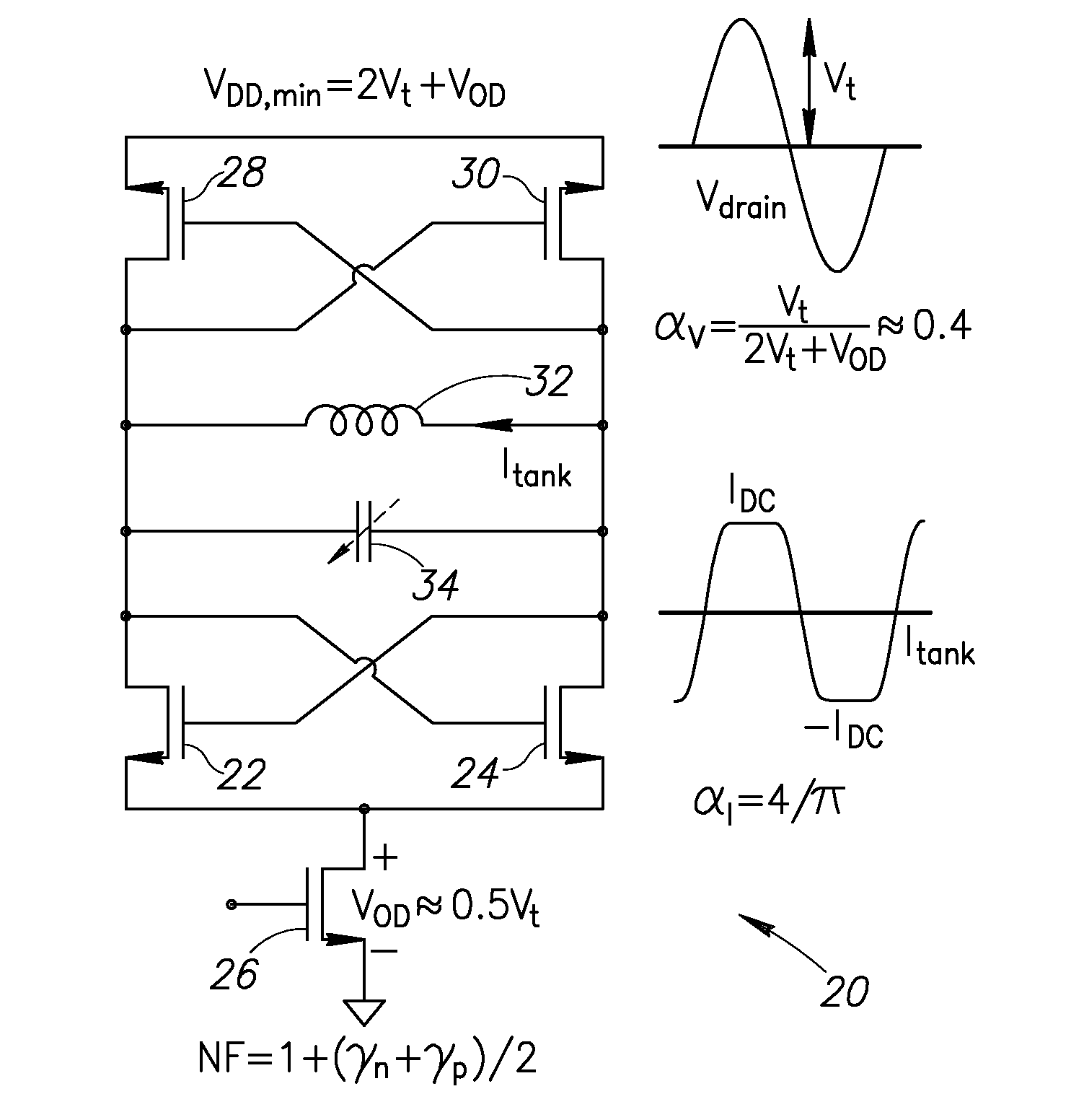
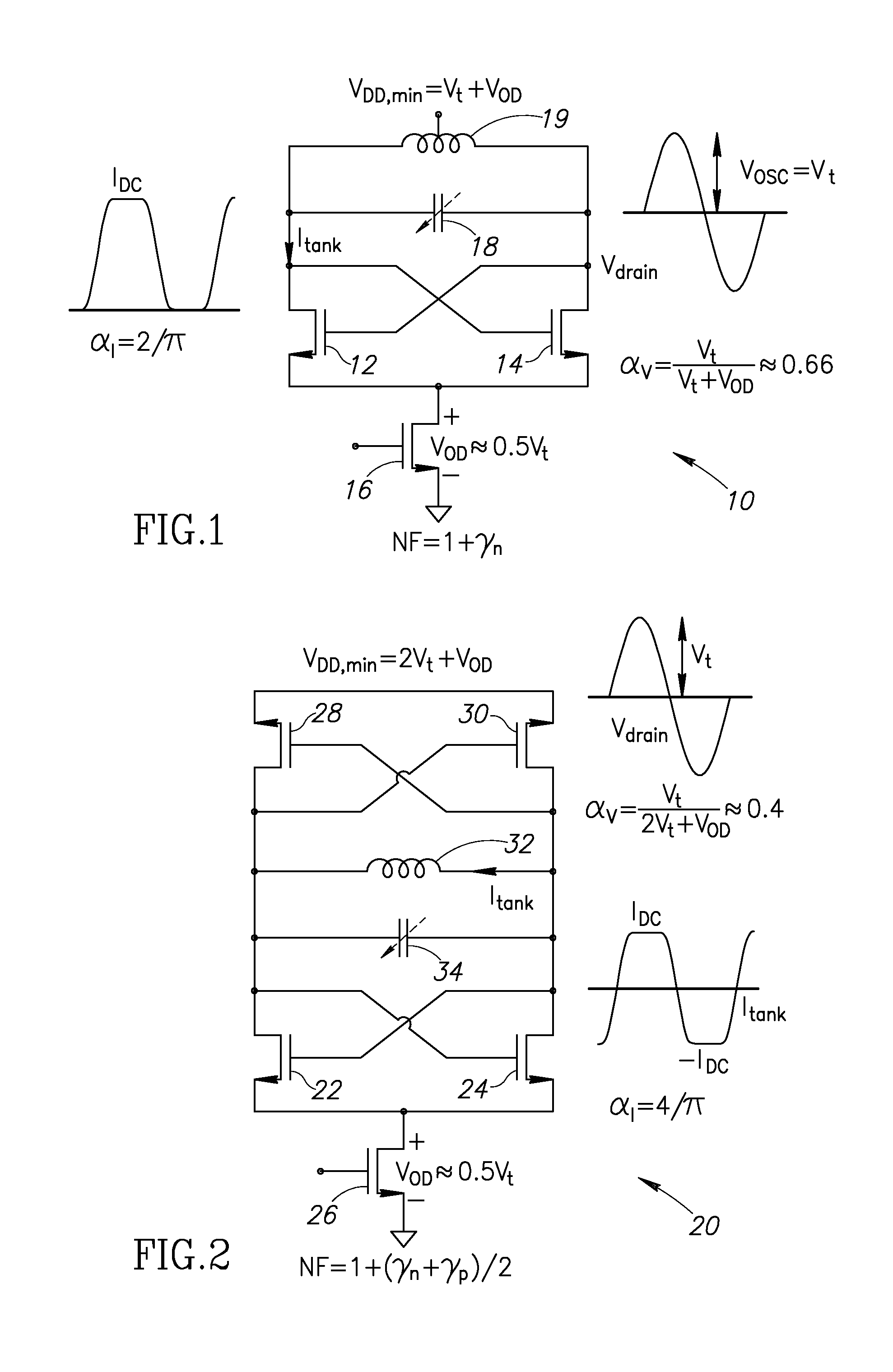
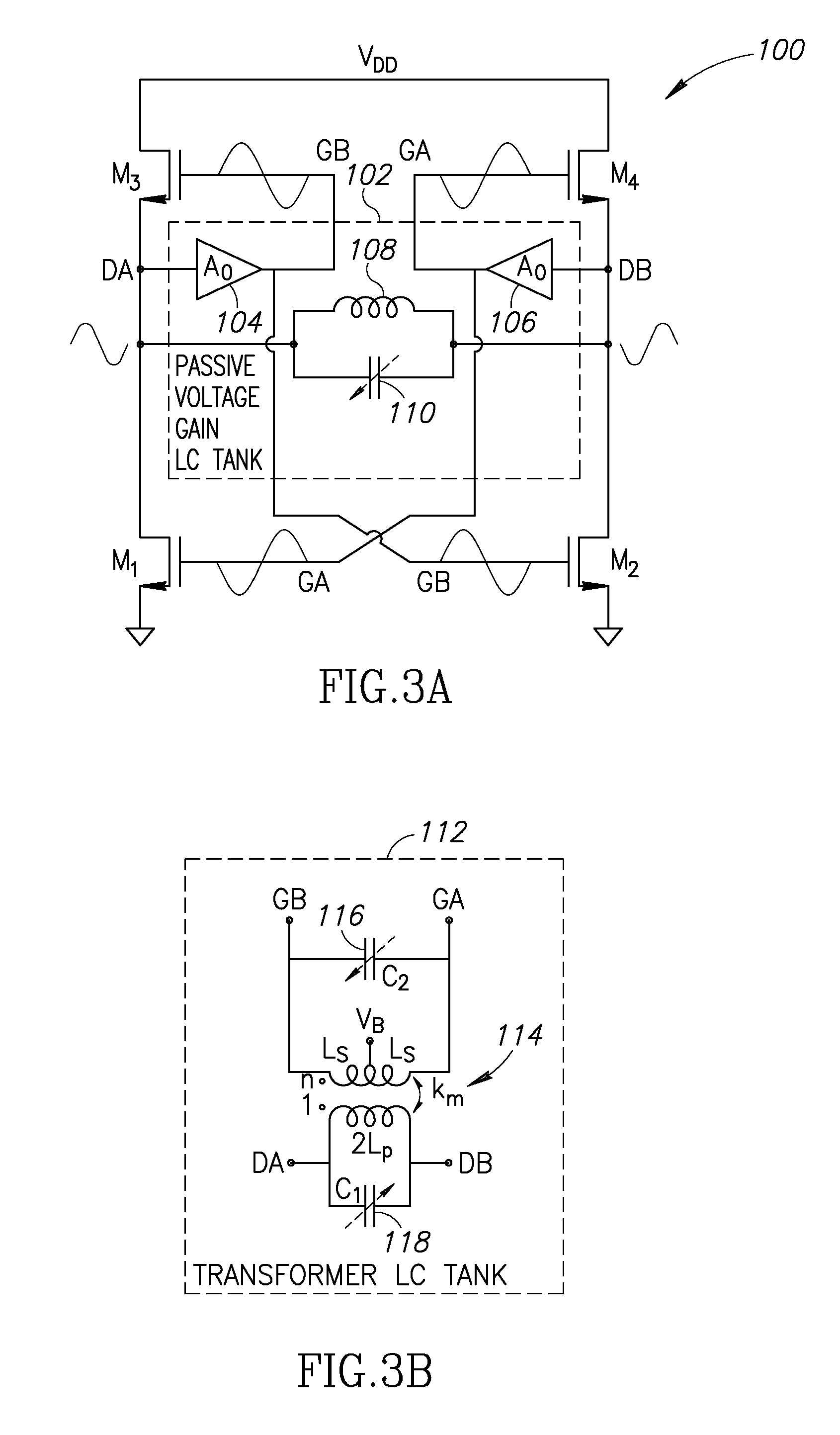
Oscillator Power Consumption Tradeoffs

[0037]The phase noise (PN) of the traditional oscillator (i.e. class-B) with an ideal current source at an offset frequency Δω from its resonating frequency ω0 can be expressed as

ℒ(Δω)=10log10(KT2Qt2αjαVPDC(1+γ)(ω0Δω)2)(1)

where, Qt is the LC-tank quality factor; αI is the current efficiency, defined as ratio of the fundamental current harmonic Iω0 over the oscillator DC current IDC; and αv is the voltage efficiency, defined as ratio of the drain oscillation amplitude Vosc (single-ended) over the supply voltage VDD. As a consequence, Vosc can be calculated by one of the following equations

Vosc=αVVDD=RinIω0=RinαIIDC  (2)

where, Rin is an equivalent input parallel resistance of the tank modeling its losses. Equation 1 demonstrates a trade-off between power consumption PDC and phase noise (PN). The PN requirements are relatively trivial for IoT applications and can be easily met by LC oscillators as long as the Barkhausen start-up criterion is satisf...


PUM


Abstract

A novel and useful RF oscillator suitable for use in applications requiring ultra-low voltage and power. The oscillator structure, employing alternating current source transistors, combines the benefits of low supply voltage operation of conventional NMOS cross-coupled oscillators together with high current efficiency of the complementary push-pull oscillators. In addition, the 1/f noise upconversion is also reduced. The oscillator can be incorporated within a wide range of circuit applications, including for example a conventional phase locked loop (PLL), all-digital phase-locked loop (ADPLL), wireline transceiver circuits and mobile devices.

Description

REFERENCE TO PRIORITY APPLICATION[0001]This application claims priority to U.S. Provisional Application Ser. No. 62 / 059,415, filed Oct. 3, 2014, entitled “Oscillators,” incorporated herein by reference in its entirety.FIELD OF THE INVENTION[0002]The present invention relates generally to oscillator circuits and in particular to an RF oscillator employing a current source that is used to reverse the direction of the LC tank current every half period.BACKGROUND OF THE INVENTION[0003]The Internet of Things (IoT) is a network or physical objects or “things” embedded with electronics, software, sensors and network connectivity that enable these devices to collect and exchange data. The IoT is expected to explode in the coming years as the hardware and software embedded in these objects and things become smaller and cheaper. A critical component of IoT devices is the transceiver which must be small in physical size, low cost and consume a relatively small amount of power due to the availa...

Claims


Application Information

Patent Timeline
Patent Type & Authority Applications(United States)
IPC IPC(8): H03B5/12
CPCH03B5/1212H03B5/124H03B5/1228H03L7/1976H03J2200/10H03B5/1215H03B5/1296H03B5/1218H03B5/1293H03B5/1281H03L7/081H03L7/0991H03B5/1265
Inventor BABAIE, MASOUDSTASZEWSKI, ROBERT BOGDAN
Owner SHORT CIRCUIT TECH LLC
Why Eureka
Try Eureka