Package structure and method of fabricating the same

Inactive Publication Date: 2016-04-14
PHOENIX PIONEER TECH
View PDF1 Cites 0 Cited by
  • Summary
  • Abstract
  • Description
  • Claims
  • Application Information

AI Technical Summary

Benefits of technology

[0018]Therefore, by providing a single wiring layer having one surface electrically connected to an electronic component and the other surface electrically connected to a plurality of conductive elements such as solder balls, the present invention has a signal transmission path that is shortened, the signal loss is reduced, and the electrical performance is improved.
[0019]Further, since only one wiring layer is formed and the conventional conductive

Problems solved by technology

That is, the design of circuits and connections is limited.
Further, the fixed size of the lead frame and the loop of the bonding wires 120 cause the QFP structure 1 to be thick and difficult to be thinned.
Furthermore, limited by the design of the lead frame, the QFP structure 1 has a small number of leads 11 and cannot meet the requirements of high I/O count and small thickness.
Although a metal board can be used to replace the lead frame and etched to form wiring layers, fine-pitch traces cannot be formed due to the limitation of etching machines.
That is, it is not possible to form traces having a width/pitch below 30/30 um.
As such, the overall structure cannot meet the requirement of small thickness, and warpage easily occurs to the overall structure.
However, during high-frequency or high-speed operation, a l

Method used


Image

  • Package structure and method of fabricating the same
  • Package structure and method of fabricating the same
  • Package structure and method of fabricating the same

Examples


Example

[0026]The following illustrative embodiments are provided to illustrate the disclosure of the present invention, these and other advantages and effects can be apparent to those in the art after reading this specification.

[0027]It should be noted that all the drawings are not intended to limit the present invention. Various modifications and variations can be made without departing from the spirit of the present invention. Further, terms such as “upper”, “lower”, “first”, “second”, “one” etc. are merely for illustrative purposes and should not be construed to limit the scope of the present invention.

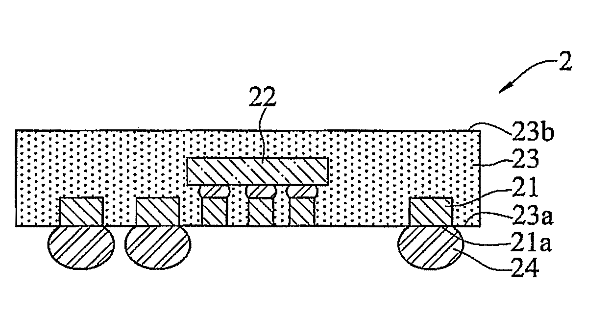
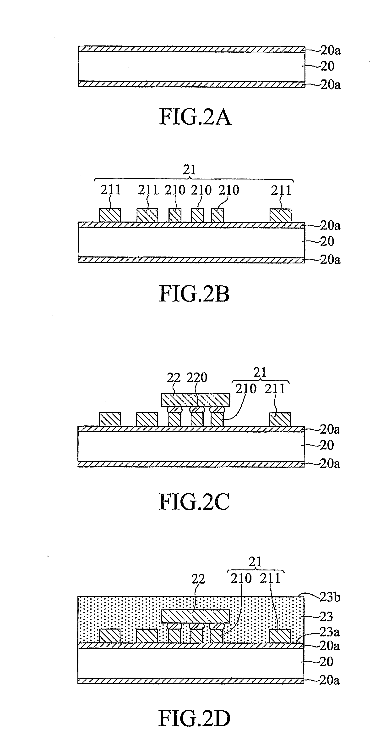
[0028]FIGS. 2A to 2F are schematic cross-sectional views showing a method of fabricating a package structure 2, 2′ of a first embodiment according to the present invention.

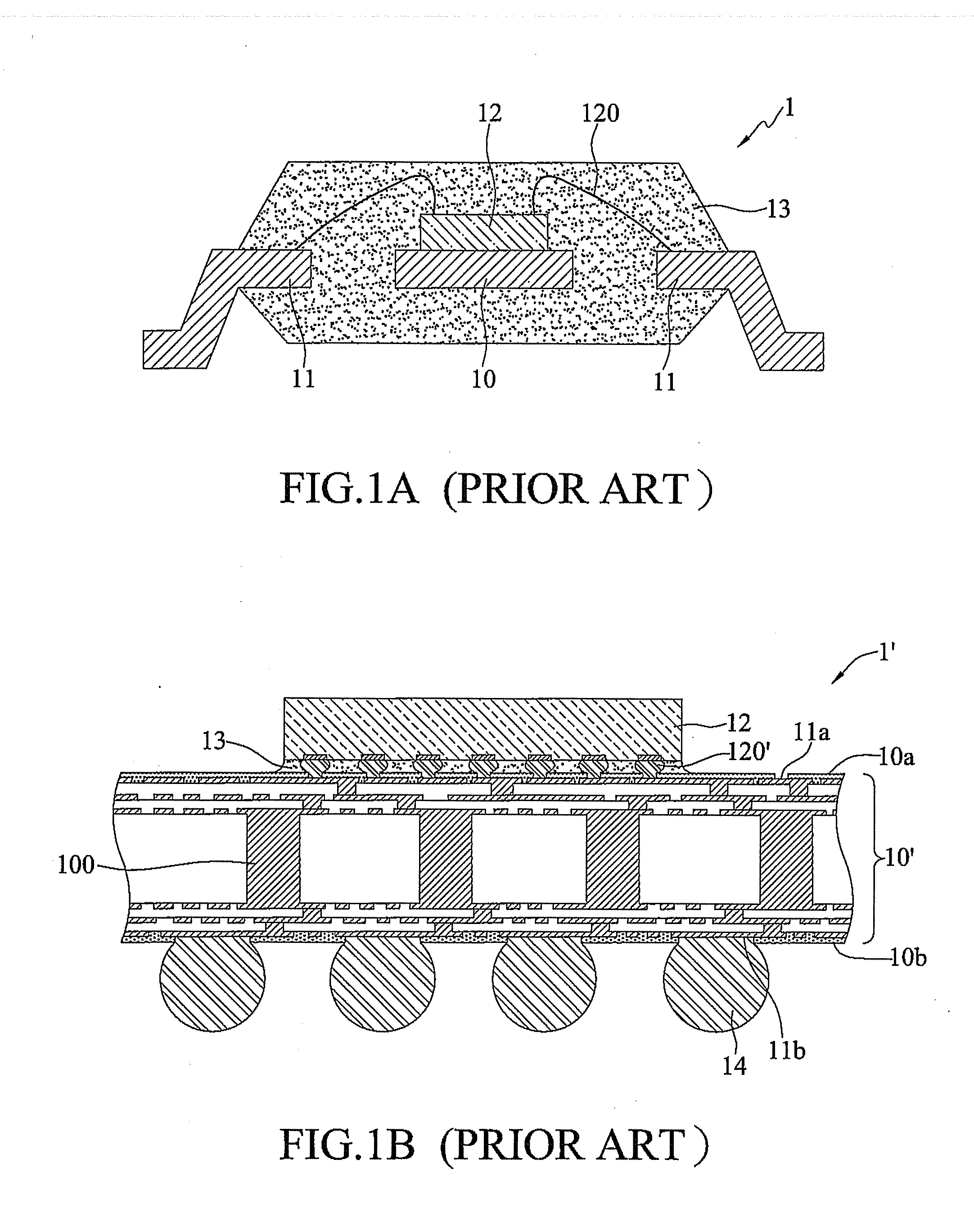
[0029]Referring to FIGS. 2A and 2B, a wiring layer 21 is formed on a carrier 20 by electroplating or deposition.

[0030]In an embodiment, the carrier 20 is a copper clad laminate having a metal layer 20a made of a copper-...


PUM


Abstract

A method for fabricating a package structure is provided, which includes the steps of: forming a wiring layer on a carrier by electroplating; disposing at least one electronic component on the wiring layer; forming on the carrier an insulating layer that encapsulates the wiring layer and the electronic component; and removing the carrier. With the single wiring layer having one surface electrically connected the at least one electronic component and the other surface electrically connected to a plurality of conductive elements, the package structure has a signal transmission path that is shortened.

Description

BACKGROUND OF THE INVENTION[0001]1. Field of the Invention[0002]The present invention relates to package structures, and, more particularly, to a package structure having a single wiring layer and a method of fabricating the same.[0003]2. Description of Related Art[0004]Along with the progress of semiconductor packaging technologies, various package types, such as ball grid array (BGA) packages, quad flat packages (QFPs) and quad flat non-leaded (QFN) packages, have been developed for semiconductor devices. These packages can be applied in smart phones, tablets, networks, laptops and so on.[0005]FIG. 1A is a schematic cross-sectional view of a conventional QFP structure 1. Referring to FIG. 1A, the QFP structure 1 has: a carrier 10; a plurality of leads 11 formed around a periphery of the carrier 10; an electronic component 12 attached to the carrier 10 and electrically connected to the leads 11 through a plurality of bonding wires 120; and an encapsulant 13 encapsulating the electr...

Claims


Application Information

Patent Timeline
IPC IPC(8): H01L23/31H01L21/288H01L23/528H01L21/683H01L21/56H01L25/16H01L21/768
CPCH01L23/3107H01L25/16H01L21/2885H01L2221/68359H01L21/6835H01L21/568H01L23/528H01L21/768H01L23/16H01L23/49541H01L23/49589H01L24/16H01L24/48H01L24/81H01L24/85H01L2224/04105H01L2224/16245H01L2224/48245H01L2224/81005H01L2224/81193H01L2224/85005H01L2924/15311H01L2924/19041H01L2924/19042H01L2924/19043H01L2924/19105H01L2924/3511
Inventor HSU, SHIH-PINGLIU, CHIH-WENWU, TANG-IHU, SHU-WEI
Owner PHOENIX PIONEER TECH
Why Eureka
Try Eureka