
Metal-Air Battery with Expandable Anode

a metal-air battery and expandable technology, applied in the field of electrochemical cells, can solve the problems of low zinc concentration, low efficiency, and high cost of flow-through zinc particle anodes, and achieve the effects of preventing zinc oxide densification, eliminating the risk of a user coming, and high volumetric energy density

Inactive Publication Date: 2016-04-21
SHARP LAB OF AMERICA INC
View PDF5 Cites 5 Cited by
  • Summary
  • Abstract
  • Description
  • Claims
  • Application Information

AI Technical Summary

Benefits of technology

The patent describes a large battery with a replaceable anode unit that has a space to expand during use. The battery uses a movable anode collector and a reservoir to keep the air-cathode connected and supply electrolyte to the slurry. This design allows for a high energy density and can be used on both sides. The battery is also safer because it eliminates the risk of user contact with the electrolyte.

Problems solved by technology

Its energy and capacity of are unchangeable as long as the battery is assembled.
However, batteries using a flow-through zinc particle anode suffer from the large amounts of electrolyte required to avoid passivation around zinc particles.
Further, the zinc particle anode requires continuous pumping, and the viscosity needed to support pumping results in a low zinc concentration.
It is difficult to realize large-scale batteries, as the slurry needs to have high loading of active material, e.g., zinc, to have high energy density, and the cell needs to contain a large amount of slurry per unit area to have a high capacity / long runtime.
However, volume expansion, slurry densification, and drying out that occur as zinc is oxidized place design constraints that limit slurry loading and anode volume / thickness.
Currently, there is no large-scale battery with exchangeable anode using slurry anode.
An open system suffers from evaporation, leading to drying out, which stops the electrochemical reaction.
Addressing these issues with a cell having an exchangeable anode unit poses safety risks, as the user may come in contact with caustic electrolyte.
For cells with a large area, however, this is not an optimal solution.

Method used


Image

  • Metal-Air Battery with Expandable Anode
  • Metal-Air Battery with Expandable Anode
  • Metal-Air Battery with Expandable Anode

Examples


Embodiment Construction

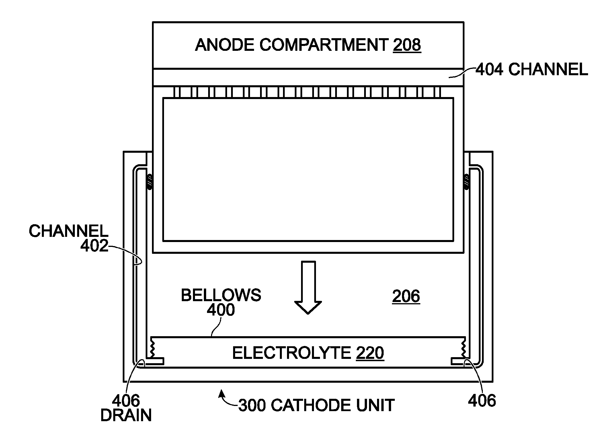
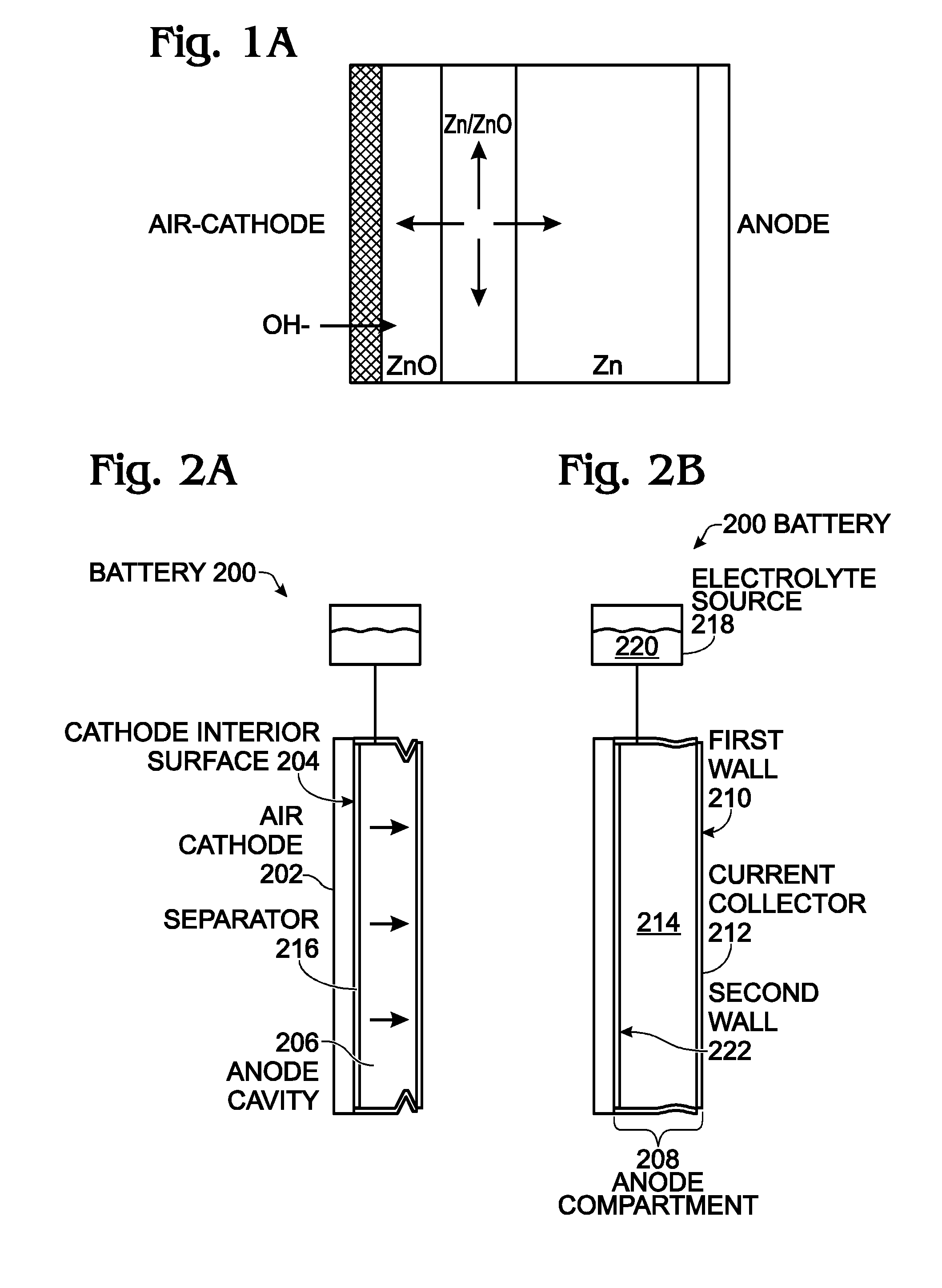
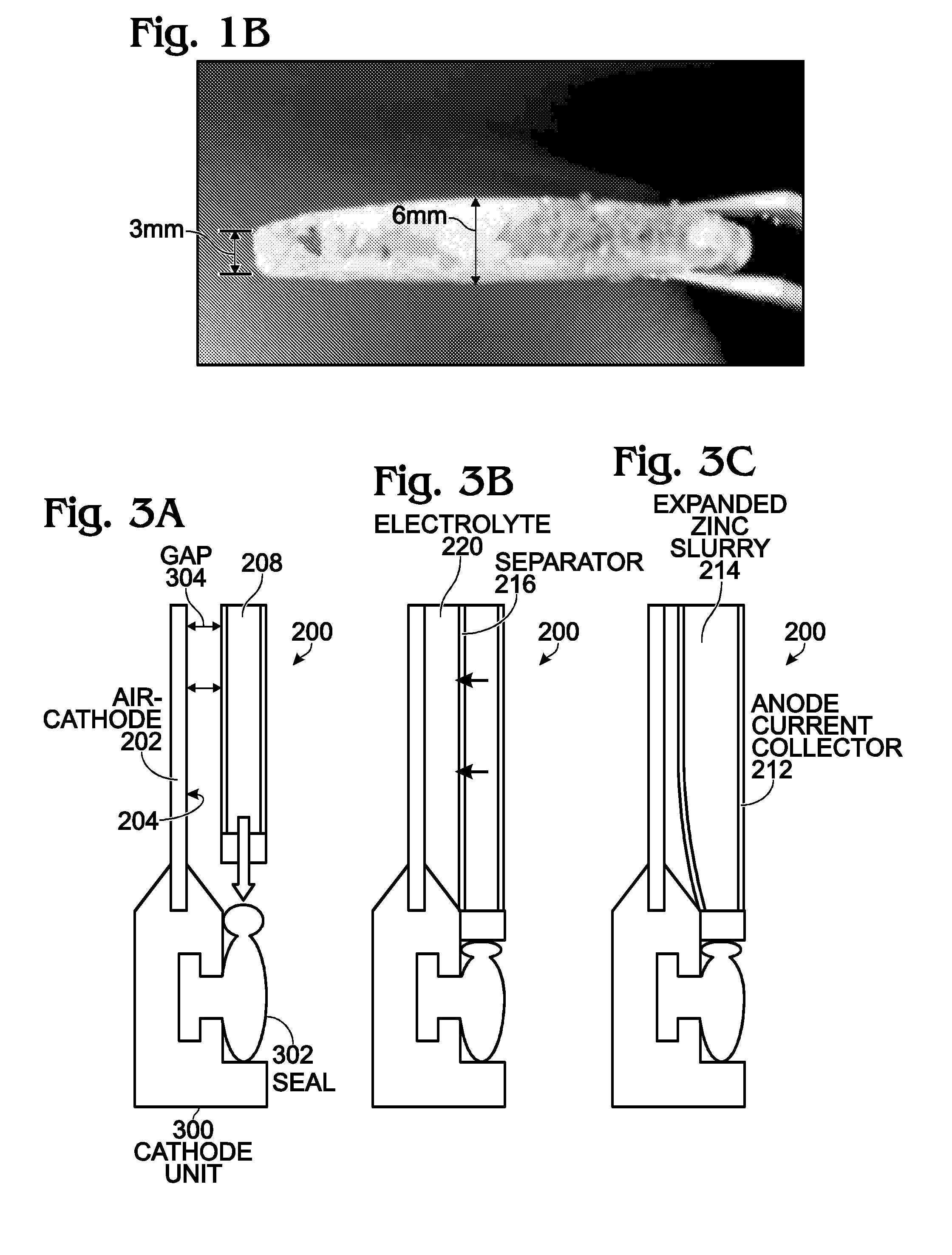
[0025]FIGS. 2A and 2B are partial cross-sectional diagrams depicting an air cathode battery with a slurry anode in the process of expansion. The battery 200 comprises an air cathode 202 having an interior surface 204. An anode cavity 206 is adjacent to the air cathode interior surface 204. An anode compartment 208 occupies the anode cavity 206, and has a wall 210 capable of expanding the anode compartment 208. The anode compartment 208 further comprises a current collector 212. A zinc slurry 214 is disposed in the anode compartment 208. An ion-permeable electrically insulating separator 216 is mounted on a wall of the anode compartment, interposed between the anode compartment 208 and the air cathode interior surface 204. A replenishable electrolyte source 218 optionally provides electrolyte 220 to the anode cavity 206.

[0026]Typically, the separator 216 has relatively large pores and is permeable to electrolyte. In addition, depending on design, the separator 216 may incorporate an ...


PUM


Abstract

An air cathode battery is provided with a slurry anode. An anode cavity is interposed between the air cathode interior surfaces, with an anode compartment occupying the anode cavity. The anode compartment has a first wall and a second wall, one or both capable of movement. An anode current collector pouch has walls adjacent to interior surfaces of the anode compartment. A zinc slurry occupies an expandable region in the anode compartment between the anode current collector pouch and the anode compartment wall interior surfaces. The anode current collector pouch first wall and second wall contract towards each other in response to expansion in the volume of zinc slurry. In one aspect, the anode compartment first and second walls expand away from each other in response to expansion in the volume of zinc oxide. A replenishable electrolyte source may be used to provide electrolyte to the anode cavity.

Description

RELATED APPLICATION[0001]The application is a Continuation-in-part of an application entitled, LARGE-SCALE METAL-AIR BATTERY WITH SLURRY ANODE, invented by Hidayat Kisdarjono, Ser. No. 14 / 673,559, filed on Mar. 30, 2015, Attorney Docket No. SLA3492;[0002]which is a Continuation-in-Part of an application entitled, AIR CATHODE BATTERY USING ZINC SLURRY ANODE WITH CARBON ADDITIVES, invented by Hidayat Kisdarjono et al., Ser. No. 14 / 473,713, filed on Aug. 29, 2014, Attorney Docket No. SLA 3415;[0003]which is a Continuation-in-Part of an application entitled, FLOW-THROUGH METAL BATTERY WITH ION EXCHANGE MEMBRANE, invented by Yuhao Lu et al Ser. No. 14 / 042,264, filed on Sep. 30, 2013, Attorney Docket No. SLA3294. All the above-referenced applications are incorporated herein by reference.BACKGROUND OF THE INVENTION[0004]1. Field of the Invention[0005]This invention generally relates to electrochemical cells and, more particularly, to an air cathode battery using a replaceable and expandabl...

Claims


Application Information

Patent Timeline
IPC IPC(8): H01M2/38H01M12/02H01M12/08H01M50/673
CPCH01M2/38H01M12/02H01M12/08H01M4/38H01M4/76H01M6/5077H01M12/06H01M50/673
Inventor KISDARJONO, HIDAYATBAUER, ALEXANDERSTECKER, GREGORYPAN, WEI
Owner SHARP LAB OF AMERICA INC
Learn More