

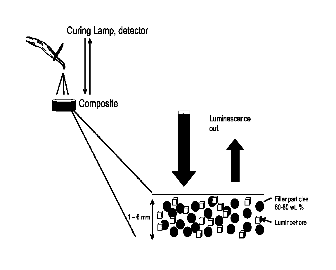
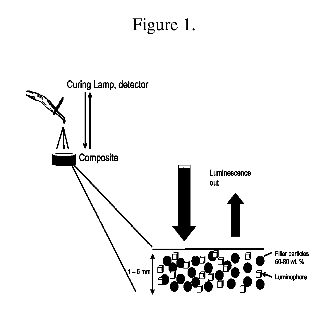
Light source, detector and luminescent composite
a technology of composites and light sources, applied in the field of photopolymerizable composites, can solve the problems of poor hardness, abrasion and wear resistance, heavy and brittleness, etc., and achieve the effects of improving durability, simple and reliable, and improving quality
- Summary
- Abstract
- Description
- Claims
- Application Information
AI Technical Summary
Benefits of technology
Problems solved by technology
Method used
Image

Examples
example 1
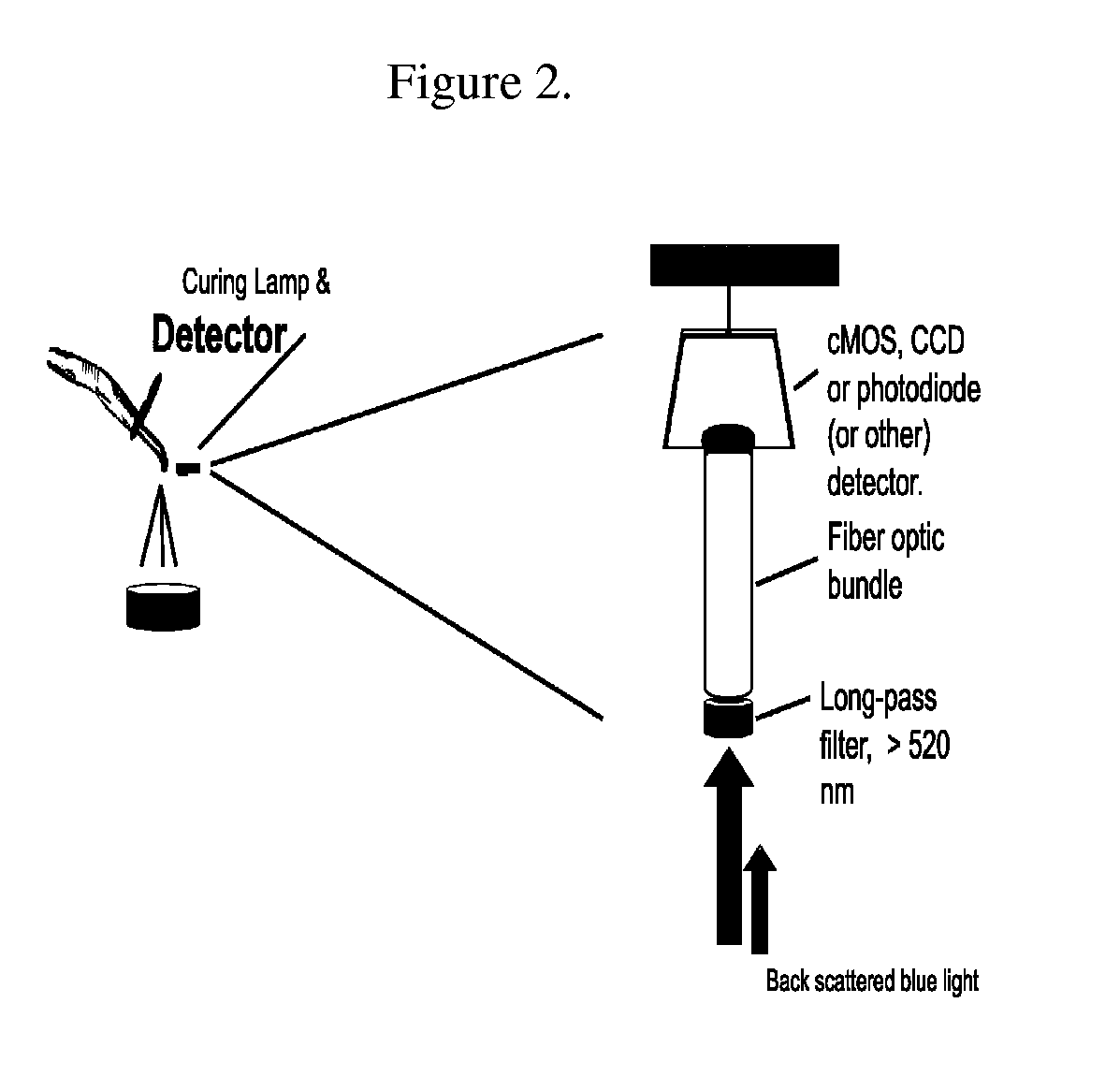
[0058]A composite paste was prepared as follows: 35.0 g of dental filler consisting of a silica-zirconia mixed-oxide prepared as described in U.S. Pat. No. 4,503,169 with refractive index 1.53, 15.0 g of a dental resin that contained the activation agent camphorquinone and 0.0112 g of HTY560 phosphor were mixed thoroughly in a centrifugal mixer. The paste was then packed into a stainless steel washer having a diameter of 5.0 mm and a specimen thickness of 1 mm. The specimen was then mounted beneath a dental lamp with the tip of the lamp held at 1 cm distance from the specimen. To collect the emitted phosphor light, a 1.5 mm fiber optic was mounted adjacent to the lamp tip and directly above the specimen. The opposite end of the fiber optic cable was mounted to a long pass filter, Schott RG645, that filtered out all wavelengths below 645 nm. The filter was mounted directly in front of the LEX-100 detector. The dental lamp was set for five second pulses. The detector voltage (luminesc...
example 2
[0059]Example 2 was performed identically to Example 1 above except that the specimen thickness was 2 mm.
example 3
[0060]Example 3 was performed identically to Example 1 above except that the specimen thickness was 3 mm.
[0061]The data collected for examples 1-3 are shown in FIG. 3. FIG. 3 shows the luminescence output versus time for specimens of thickness 1 mm (a), 2 mm (b) and 3 mm (c), respectively. The exposures were done at five second intervals and repeated five to six times. The voltage signal is pulsed due to pulsations inherent to the dental lamp. The data indicate that the luminescence output of the composite (the upper curve) changes during exposure, initially increasing but leveling off after a short time. The time at which the signal levels off increases with increasing sample thickness. The data indicate that the luminescence output can be used to measure or integrate the total light flux reaching the specimen, and is dependent upon time and specimen thickness. The interpretation of the signals observed with respect to indicating cure of the composite(s) is explained vide supra.
PUM
| Property | Measurement | Unit |
|---|---|---|
| Wavelength | aaaaa | aaaaa |
| Degree of polymerization | aaaaa | aaaaa |
| Wavelength | aaaaa | aaaaa |
Abstract
Description
Claims
Application Information