Communicating through physical vibration

Active Publication Date: 2016-04-28
THE BOARD OF TRUSTEES OF THE UNIV OF ILLINOIS
View PDF6 Cites 8 Cited by
  • Summary
  • Abstract
  • Description
  • Claims
  • Application Information

AI Technical Summary

Benefits of technology

The patent text describes a technology for communicating through physical vibration, which is different from other communication methods like RF and Bluetooth. The technology aims to address security concerns associated with these methods. The patent describes various components and methods for creating a system that can transmit and receive data through vibration. The technology can be used in various applications like smartphones, wearables, and other devices. The patent also includes various drawings and graphs to show the performance of the technology. The technical effects of the patent are improved security and efficiency in data communication through physical vibration.

Problems solved by technology

These technologies, however, are known to suffer from security concerns in being susceptible to interception out of the air if within signal range.

Method used


Image

  • Communicating through physical vibration
  • Communicating through physical vibration
  • Communicating through physical vibration

Examples


Embodiment Construction

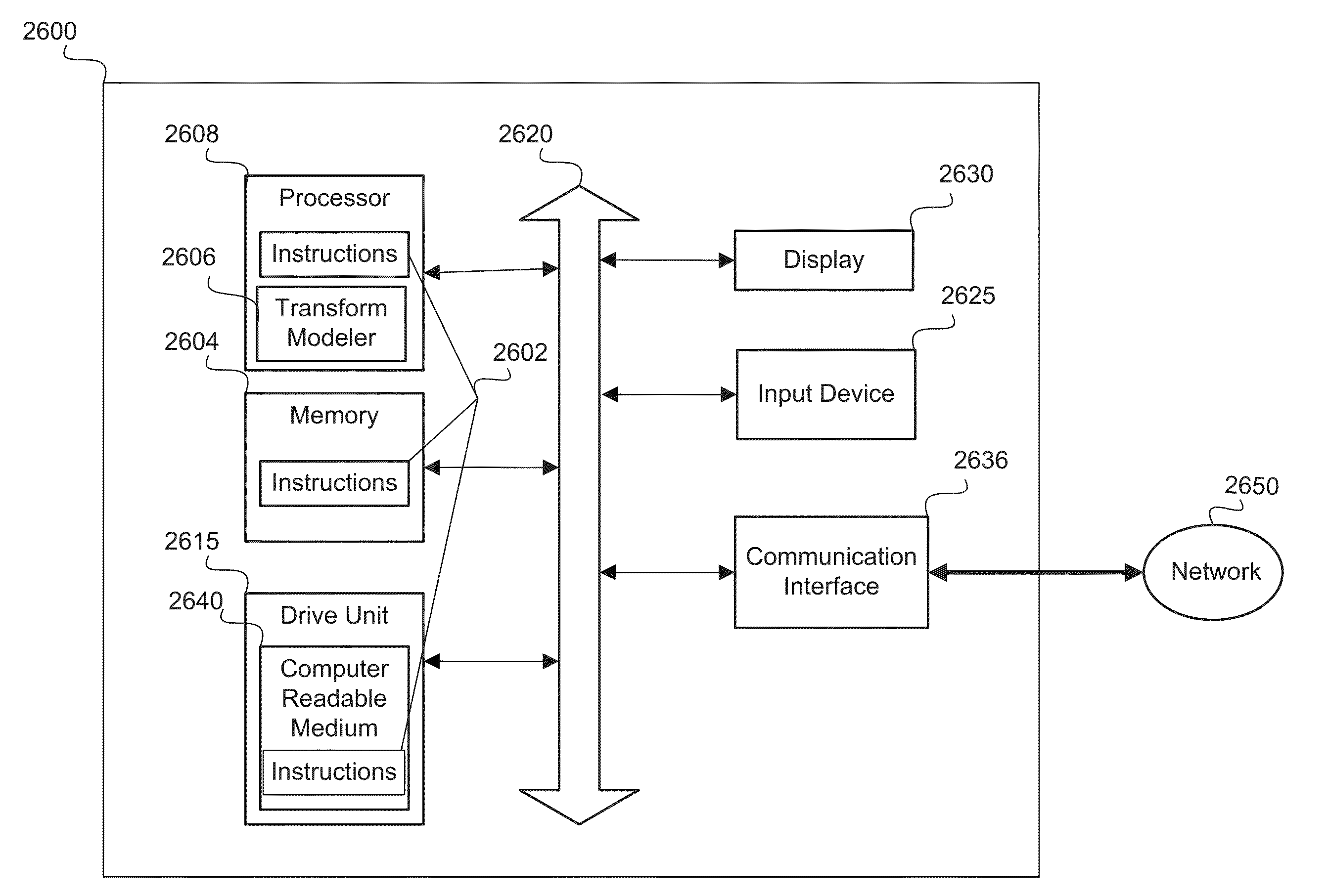
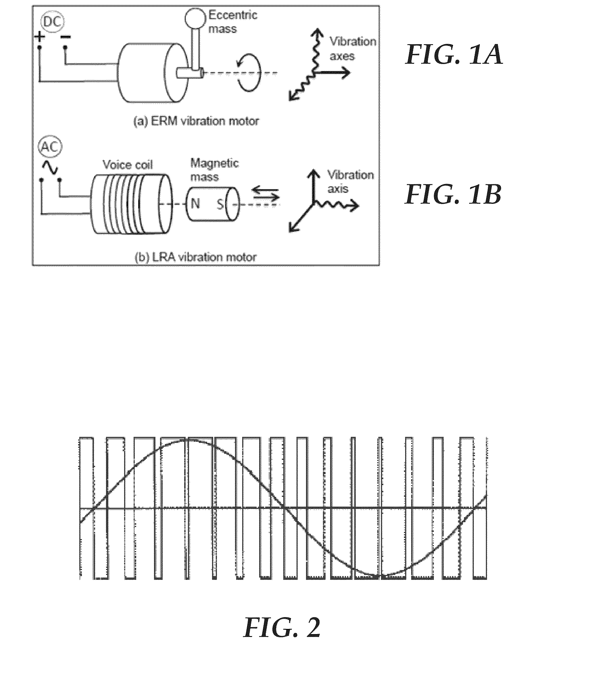
[0043]By way of introduction, the present disclosure relates to communicating through vibration between, for example, two electronic devices. In one embodiment, a data transmitter includes a vibration motor and a switch to regulate voltage from a direct-current (DC) power supply to the vibration motor. A microcontroller generates a pulse width modulation (PWM) signal with which to drive the switch and regulate the voltage to the vibration motor in a sinusoidal manner, to generate data as symbols from vibrations that form a series of bits from the vibration motor.

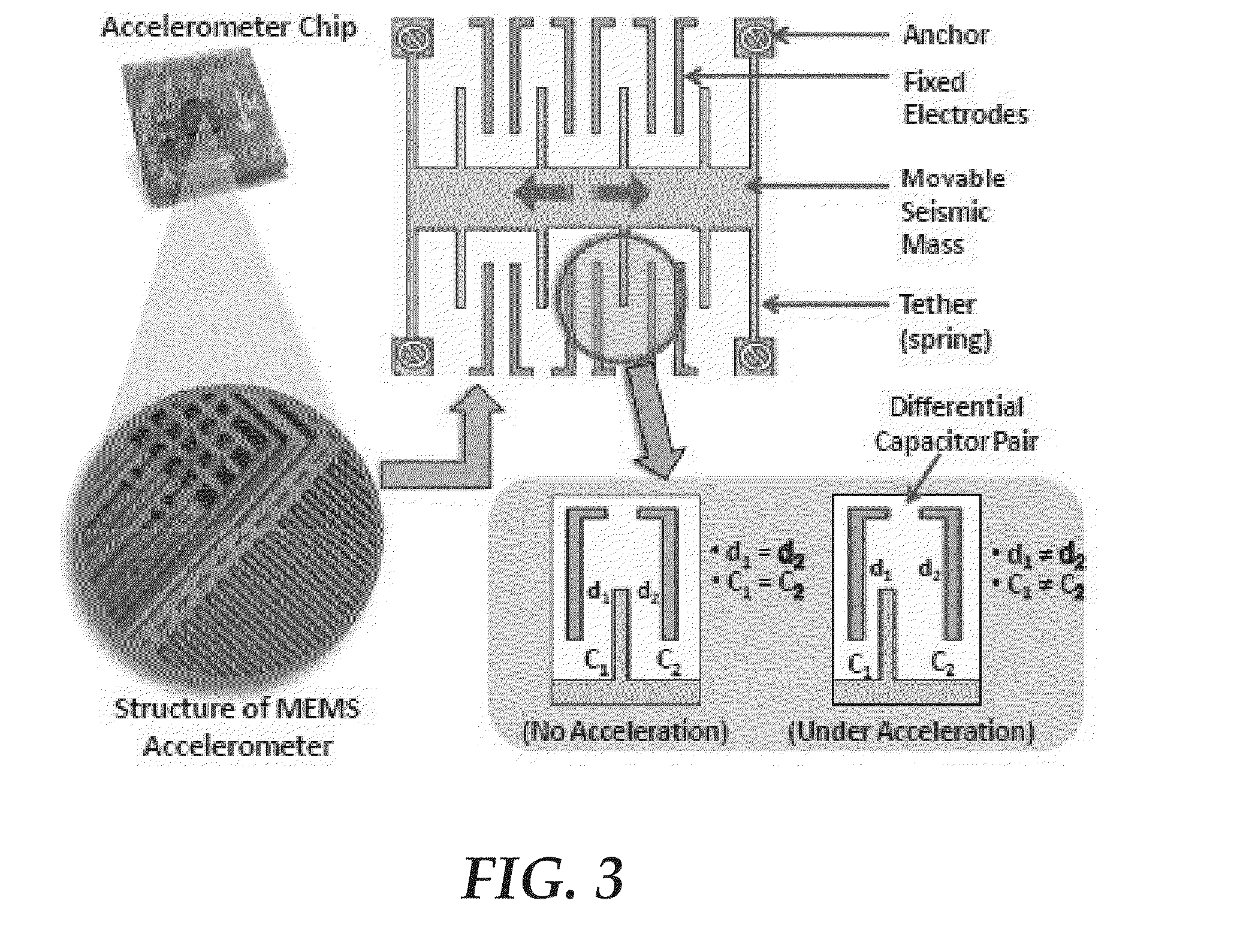
[0044]In one embodiment, a data receiver includes a vibration sensor that samples data from vibrations in an incoming signal at a predetermined sampling rate. The incoming signal may be received from direct physical contact with a data transmitter or through physical contact with a physical channel (such as a table top) with which the data transmitter also has physical contact. A microcontroller, coupled to the vibration sen...


PUM


Abstract

A data transmitter includes a vibration motor and a switch to regulate voltage from a direct-current (DC) power supply to the vibration motor. A microcontroller generates a pulse width modulation signal with which to drive the switch and regulate the voltage to the vibration motor in a sinusoidal manner, to generate data as symbols from vibrations that form a series of bits from the vibration motor. The microcontroller may also cancel and jam a sound of vibration (SoV) created by the vibration motor. A data receiver includes a vibration sensor to sample data from vibrations in an incoming signal at a predetermined sampling rate, and a microcontroller, coupled to the vibration sensor, to control the sampling rate through an inter-integrated circuit (I2C) protocol or the like. A memory card, coupled to the microcontroller, stores the data with a serial peripheral interface (SPI) protocol or the like.

Description

REFERENCE TO EARLIER FILED APPLICATION[0001]This application claims the benefit under 35 U.S.C. §119(e) of U.S. Provisional Patent Application No. 62 / 067,176, filed Oct. 22, 2014, which is incorporated herein, in its entirety, by this reference.TECHNICAL FIELD[0002]The present disclosure relates to communicating through physical vibration.BACKGROUND[0003]Various near field communication technologies exist today, some of which employ radio frequency (RF) modalities, including near field communication (NFC), infrared, Bluetooth® of Bluetooth Sig, Inc. and WiFi® of the WiFi® Alliance. These technologies, however, are known to suffer from security concerns in being susceptible to interception out of the air if within signal range.BRIEF DESCRIPTION OF THE DRAWINGS[0004]A more particular description of the disclosure briefly described above will be rendered by reference to the appended drawings. Understanding that these drawings only provide information concerning typical embodiments and ...

Claims


Application Information

Patent Timeline
IPC IPC(8): H04L25/49H04B1/16H04B1/04
CPCH04L25/4902H04B1/16H04B1/0475H04B1/04H04B11/00
Inventor ROY, NIRUPAMCHOUDHURY, ROMIT ROYGOWDA, MAHANTH K.
Owner THE BOARD OF TRUSTEES OF THE UNIV OF ILLINOIS
Why Eureka
Try Eureka