Tank container for transport and storage of cryogenic liquefied gases

a technology for cryogenic liquefied gas and tank containers, which is applied in the direction of transportation and packaging, container discharging methods, and container filling under pressure, etc., can solve the problems of capital intensive expansion of gas pipeline networks, high capital expenditure on gas pipeline construction, and low vacuum for traditional cryogenic tank insulation to achieve the effect of low maintenance, high transport capacity and low tare weigh

Active Publication Date: 2016-05-05
ASPEN AEROGELS INC
View PDF3 Cites 0 Cited by
  • Summary
  • Abstract
  • Description
  • Claims
  • Application Information

AI Technical Summary

Problems solved by technology

The traditional insulation of cryogenic tanks is considered to still require a significant low vacuum for successful operation.
Expansion of gas pipeline network is capital intensive and is difficult in areas with low consumption population density; the supply of liquefied gas provides the introduction of gas in areas where the supply pipeline is possible only after a long period of growth in consumption.
Construction of gas pipelines is capital intensive and requires at least a basic supply of gas to enough powerful customers.
This condition is unavailable in many locations in a real short time.
Production of such double container and vacuuming of the dead space is technologically very demanding and expensive.
Thus, the container must be serviced annually for vacuuming dead space, which can last several weeks, while all the time necessary for restoring the insulation the tank is useless.

Method used


Image

  • Tank container for transport and storage of cryogenic liquefied gases
  • Tank container for transport and storage of cryogenic liquefied gases
  • Tank container for transport and storage of cryogenic liquefied gases

Examples


implementation case 1

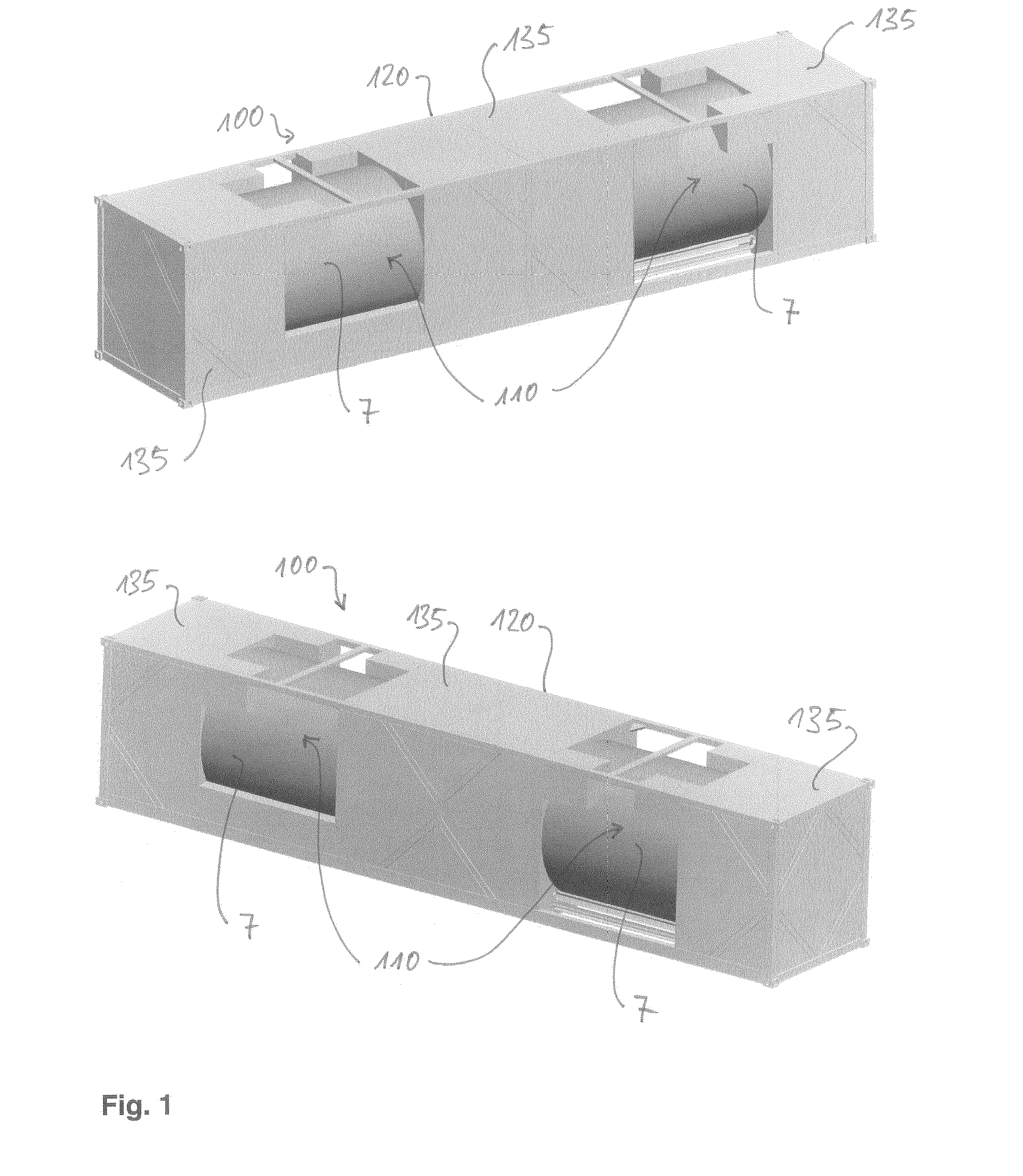
[0039]>>Intermodal100 CRYOTAINER 34000 LNG / 40′ (FIG. 1) is intended for the long range transportation of liquefied natural gas and is assembled of two horizontal vessels 110 of 16.800 liter clamped into a standard frame 120 for a 40-foot (˜12 m long; in the following text as 40′) container.

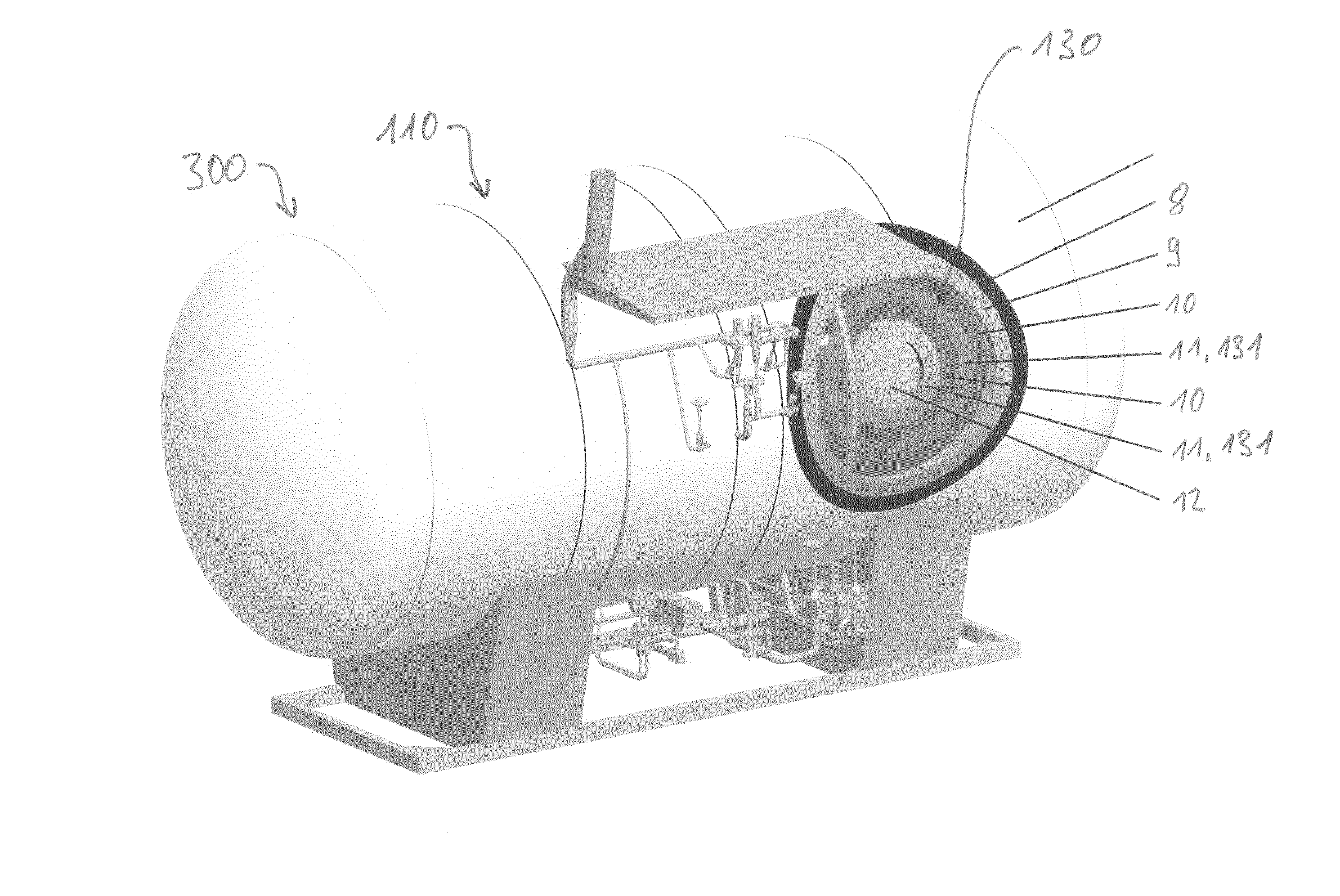
[0040]Each pressure vessel 110 is horizontally embedded in the standard ISO 40′ container frame 120′. The pressure vessel 110 is defined of an internal shell 12 which is covered by an external insulation coating formed by a cover sheet 7. The space between shell 12 and coating 7 is filled with an 7 insulation arrangement 130 comprising a combination of insulating materials. (FIG. 7a, FIG. 7b). The insulation arrangement 130 from the inside towards the outside consists of at least one (two according to FIG. 7b) set 131s of several (five with a thickness of 10-mm, as indicated in FIG. 7b) nanostructure insulation layers 11 of cryogenic insulation based on an aerogel composition (total 100 mm). In th...

implementation case 2

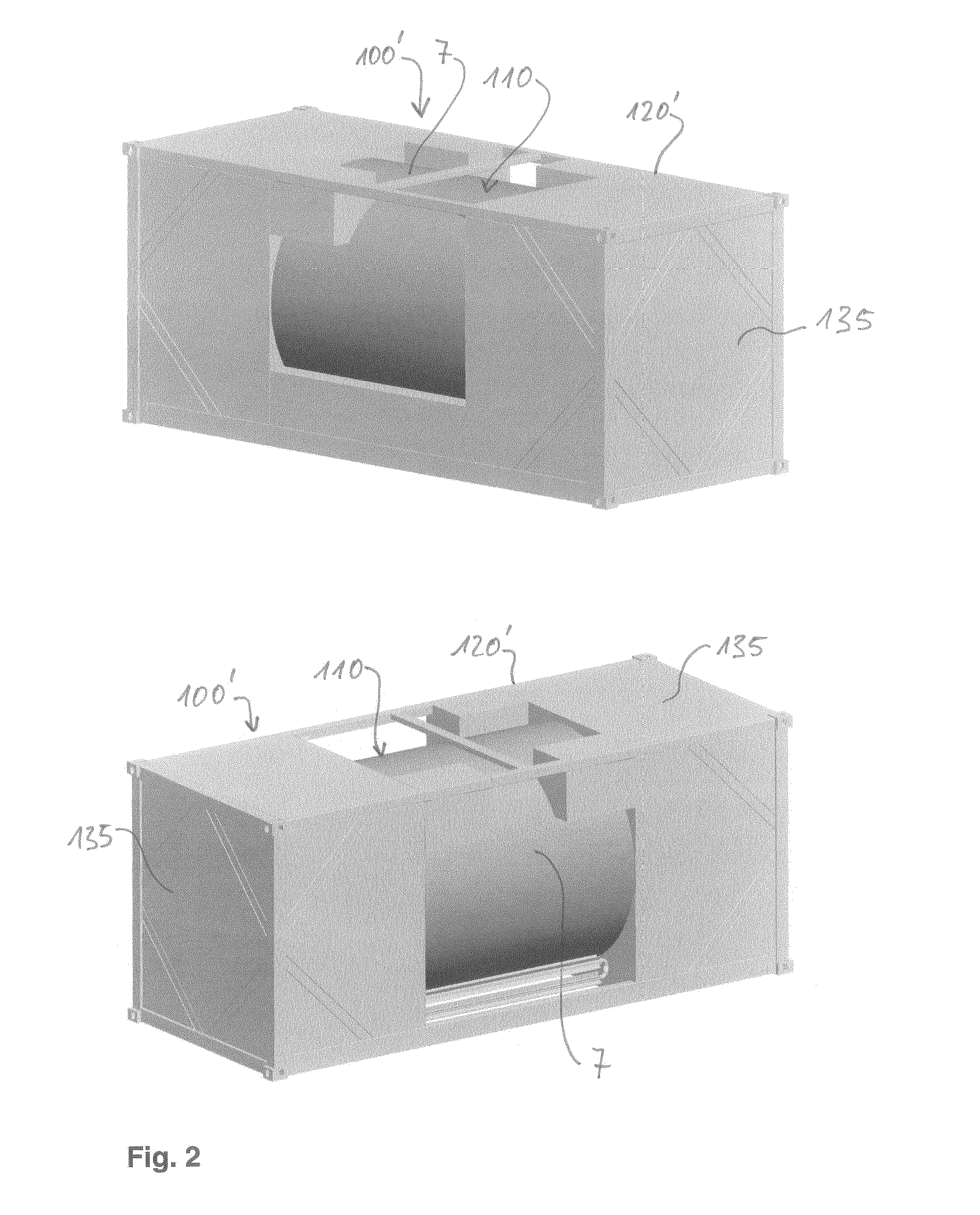
[0056]Intermodal unit CRYOTAINER 16800 LNG / 20′ (FIGS. 2 and 5) is intended for local transport of liquefied natural gas and is composed of a horizontal vessel 110 of 16.800 liter volume clamped into a standard 20-foot (some 6 m; vas 20′ in the following text) frame 120′.

[0057]Pressure vessel 110 is horizontally embedded in the standard ISO 40′ container frame 120′. All 5 further features and embodiments of the insulation arrangement 130, supports 30 and the saddle structure 121 described above in connection with implementation case 1 also apply to the tank container 100′ with a single vessel 110 according to implementation case 2 (FIGS. 2 and 5).

implementation case 3

[0058]The vertical stationary pressure vessel 200 CARD 8600 LNG (FIG. 3) is intended for storage and distribution of liquefied natural gas. The volume of the vessel is 8.600 liter (the family extends from 8.600 to 15.000 liter). This vessel presents a cost effective alternative to local supply of customers on low population density areas, where a pipeline solution would prove not feasible due to high capital involvement. The use of liquefied natural gas in supply of medium and small consumers can present an option also for the supply of vehicles in traffic where it is one of the cleanest and environmentally most favorable solutions. All further features and embodiments of the insulation 130 described above in connection with implementation cases 1 and 2 also apply to the vertical stationary vessel 200 according to implementation case 3.


PUM

PropertyMeasurementUnit
temperatureaaaaaaaaaa
temperaturesaaaaaaaaaa

Abstract

The invention relates to a tank container (100; 100′) for the transport and storage of cryogenic liquefied gas, comprising a framework (120) and a cylindrical vessel (110) connected to the frames work (120), wherein the vessel (110) is covered by a superinsulation arrangement (130) based on an aerogel composition, and the vessel (110) is connected to the framework (120) by a clamping device (30) which is adapted to allow for a relative movement between the framework (120) and the vessel (110) due to thermal expansion or contraction of the vessel (110).

Description

CROSS-REFERENCES TO RELATED APPLICATIONS[0001]This application is a continuation of U.S. patent application Ser. No. 14 / 377,629, filed Aug. 8, 2014; which is a National Stage Application under 35 U.S.C. §371 of PCT / EP2013 / 052559 filed on Feb. 8, 2013; which claims priority to the Slovenian International Patent Application SI201200040 filed on Feb. 10, 2012; all of which are hereby incorporated by reference in their entirety as if fully set forth.DESCRIPTION[0002]The invention relates to the development of cryogenic equipment for transport and storage of liquefied gases where the family of cryogenic equipment for transport and storage consist of horizontal and vertical vessels and transportable—mobile equipment in ISO containers. The invention specifically relates to a tank container for the transport and storage of cryogenic liquefied gas, comprising a framework and a cylindrical vessel connected to the framework.KNOWN STATE OF DEVELOPMENT[0003]The current existing technological sol...

Claims


Application Information

Patent Timeline
Patent Type & Authority Applications(United States)
IPC IPC(8): F17C3/02F17C13/00F17C3/04
CPCF17C3/022F17C2203/03F17C13/001F17C3/04F17C2205/0192F17C2201/0109F17C2201/032F17C2201/035F17C2201/054F17C2203/0308F17C2203/0325F17C2203/0329F17C2203/0629F17C2203/0643F17C2203/0697F17C2205/0107F17C2205/0126F17C2205/013F17C2205/0332F17C2209/221F17C2221/011F17C2221/013F17C2221/014F17C2221/016F17C2221/033F17C2223/0161F17C2223/033F17C2250/0408F17C2250/043F17C2250/0626F17C2260/012F17C2260/013F17C2260/033F17C2270/0102F17C2270/0165F17C2270/0173F17C5/02
Inventor MILAN, ZRIMMIHAEL, GRUDEN
Owner ASPEN AEROGELS INC
Why Eureka
Try Eureka