Method and system for imaging a molecular strand

a molecular strand and imaging technology, applied in the field of molecular strand imaging, can solve the problems of deteriorating the effective resolution of images to a value that is worse than the optical resolution, additional difficulties in beam alignment, and small effective focus size, so as to maximize the contrast of the strand, minimize the line thickness of the strand, and maximize the effect of overlap

Active Publication Date: 2016-05-19
LUMICKS DSM HLDG BV
View PDF12 Cites 11 Cited by
  • Summary
  • Abstract
  • Description
  • Claims
  • Application Information

AI Technical Summary

Benefits of technology

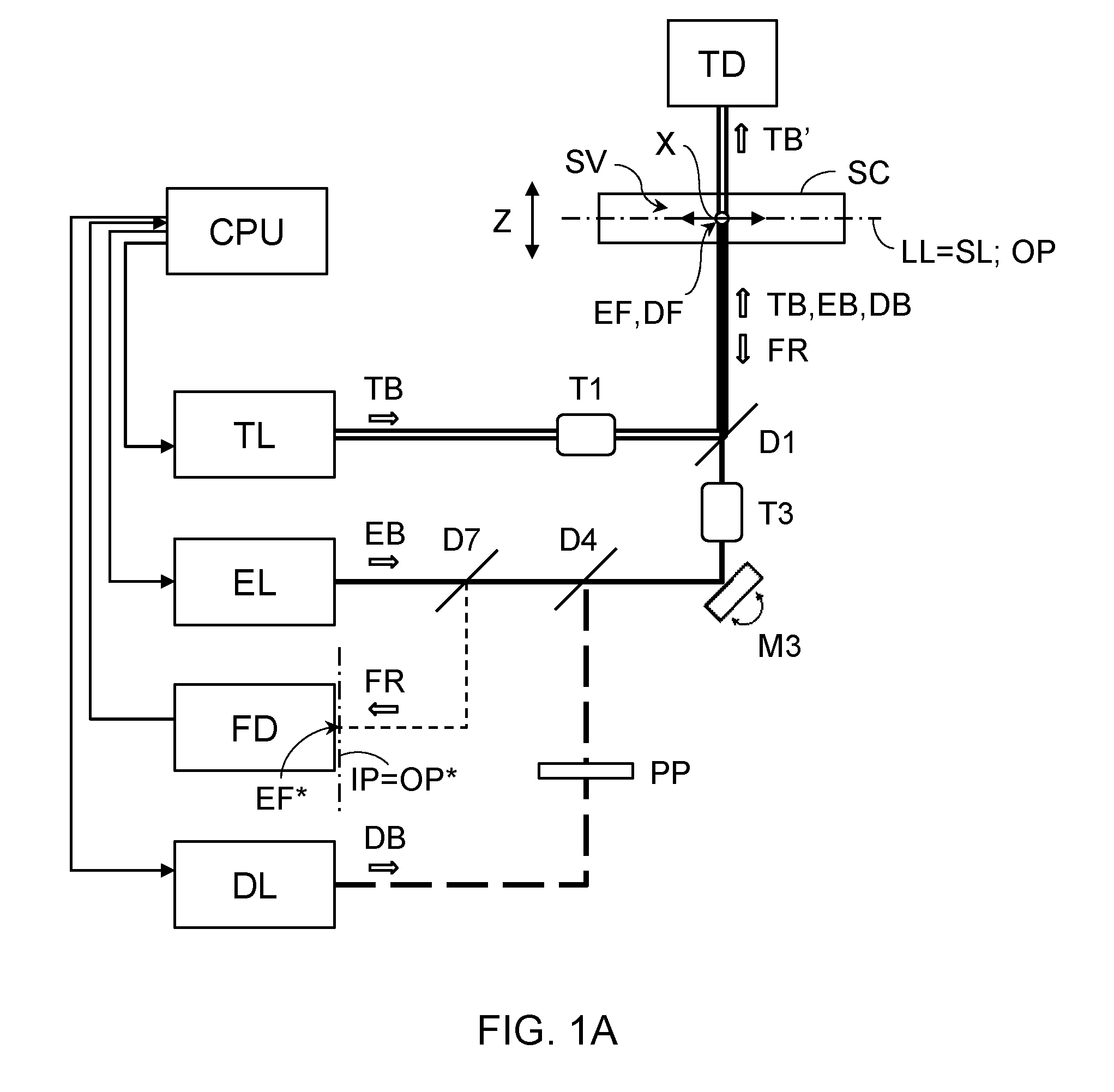
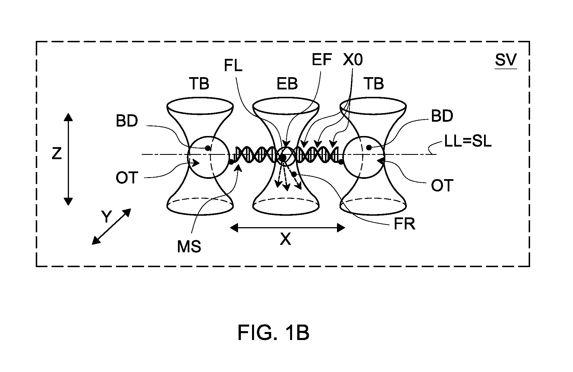
[0009]By extending the molecular strand along a straight (one-dimensional) trapping line, scanning a probe beam along a scanning line parallel to the trapping line, and aligning the trapping line and scanning line to coincide, the molecular strand can be accurately imaged in a controlled and reproducible manner. It is recognized that the one-dimensional trapping and scanning is specifically tailored for imaging a molecular strand which can be considered a one-dimensional object for imaging purposes. Because only the dimension of the molecular strand is scanned, the scanning can be better controlled, the imaging more accurate, and faster. In contrast, the prior art of e.g. US 2011 / 0201509 and US 2012 / 0002031 essentially relies on two-dimensional fluorescence imaging and not a one-dimensional scanning line. The mention of STED microscopy does not imply one-dimensional scanning along a trapping line or otherwise. In particular, it is noted that STED is conventionally used for producing two-dimensional images as described for example in the articles by Donnert et al. (PNAS, part 103, nr. 31, p. 11440) and Gael Moneran et al. (Optics Express, part 18, nr. 2, p. 1302).
[0010]The use of a one dimensional scanning line provides also additional advantages. For example, by repeatedly scanning the excitation focus back and forth along the scanning line, the fluorescence response can be recorded as a function of the signal can be integrated over multiple scans to increase the signal. Alternatively or in addition, the signal can also be recorded as a function of time to track changes of the molecular strand or molecular complex.
[0011]By providing a second beam which decreases the spatial spread of the excited fluorophores by stimulated emission depletion (STED) of the fluorophore, resolution of the imaging can be improved beyond the diffraction limit, e.g. also depending on power in STED beam (see below). However, the smaller effective focus size can provide additional difficulties in beam alignment. By providing the depletion profile with a stripe or plane of minimum intensity extending in a direction perpendicular to the trapping line, as opposed to a round donut shaped depletion profile, sensitivity to misalignment of the beam can be decreased , in particular for the presently disclosed one-dimensional scanning of the strand. By having a STED profile shaped as a line or plane perpendicular to the direction of the extended strand, fluctuations in the positioning of the beam and / or strand in the said perpendicular direction may have a less or negligible influence on the fluorescence signal.
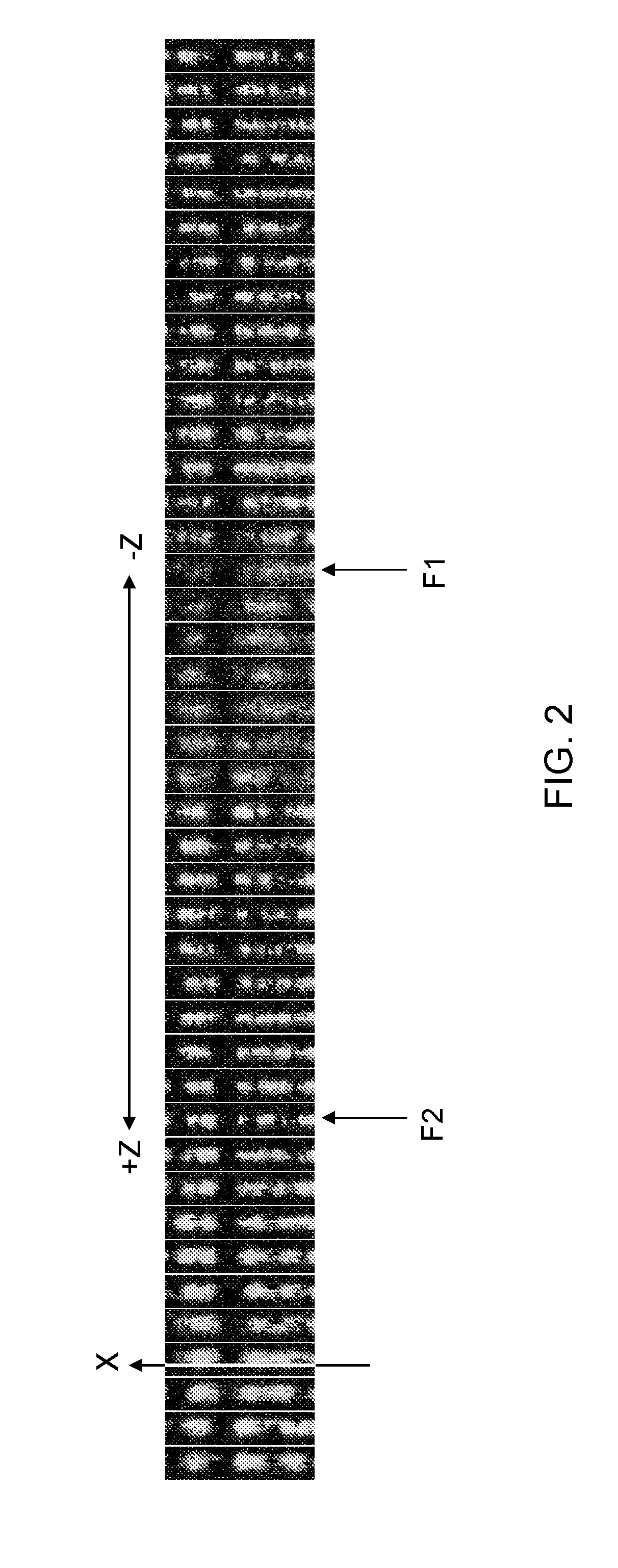
[0013]One method for the alignment (in Z) comprises recording a series of two dimensional images of the stained strand for different axial positions of the optical traps with respect to the scanning line. The inventors find that by minimizing a line thickness of the strand (XY) in the images and / or by maximizing a contrast of the strand in the images while varying a position of the object plane with respect to the trapping line (in Z), an optimal overlap between the trapping line and scanning line can be found. Advantageously, the optical traps can furthermore allow adjusting and measuring of the tensile force exerted on the strand. The inventors find that by exerting a tensile force on the strand large enough to suppress the Brownian fluctuations below the imaging resolution (in the case of Lambda DNA, of length of 16.4 of more than 5 pN, preferably more than 10 pN, the imaging resolution (Full-width half maximum of the recorded signal FWHM) can be improved, in particular the resolution can be optimized in conjunction with the STED beam improvement.
[0016]By using a confocal setup, background light originating away from the focal plane (object plane) can be filtered. By trapping and extending the entire strand in the focal plane, the strand can be imaged without moving the focal plane with improved background rejection, e.g. labelled proteins (fluorophores) in the background. Advantageously, the strand does not have to be moved to another location where no proteins in solution are present, or these proteins need not be flushed away. This enables measurements of the strand in higher concentrations of labelled proteins, e.g. a factor 100 times higher than with wide field imaging, better mimicking in vivo conditions.

Problems solved by technology

However, the smaller effective focus size can provide additional difficulties in beam alignment.
This blurring deteriorates the effective resolution of images to a value that is worse than the optical resolution.
If a second object is present at a distance closer than the resolution, and the two objects are imaged at the same time, than one can no longer distinguish the two objects, and thus cannot localize them.

Method used


Image

  • Method and system for imaging a molecular strand
  • Method and system for imaging a molecular strand
  • Method and system for imaging a molecular strand

Examples


Embodiment Construction

[0036]Unless otherwise defined, all terms (including technical and scientific terms) used herein have the same meaning as commonly understood by one of ordinary skill in the art to which this invention belongs as read in the context of the description and drawings. It will be further understood that terms, such as those defined in commonly used dictionaries, should be interpreted as having a meaning that is consistent with their meaning in the context of the relevant art and will not be interpreted in an idealized or overly formal sense unless expressly so defined herein. In some instances, detailed descriptions of well-known devices and methods may be omitted so as not to obscure the description of the present systems and methods. Terminology used for describing particular embodiments is not intended to be limiting of the invention. As used herein, the singular forms “a”, “an” and “the” are intended to include the plural forms as well, unless the context clearly indicates otherwise...


PUM

PropertyMeasurementUnit
tensionsaaaaaaaaaa
diameteraaaaaaaaaa
diameteraaaaaaaaaa

Abstract

The present disclosure concerns a method and system for imaging a molecular strand (MS). The method comprises providing a sample volume (SV) comprising the strand (MS); providing an excitation beam (EB) having an excitation focus (EF) in the sample volume (SV); scanning the excitation focus (EF) in the sample volume (SV) along a one dimensional scanning line (SL); trapping an end of the strand (MS) in the sample volume (SV) and extending the strand (MS) along a one-dimensional trapping line (LL) parallel to the scanning line (SL); aligning the trapping line (LL) to coincide with the scanning line (SL) to have the scanning excitation focus (EF) coincide with the strand (MS); and recording the fluorescence response (FR) as a function of a plurality of distinct scanning positions (X0) of the excitation focus (EF) along the scanning line (SL).

Description

TECHNICAL FIELD AND BACKGROUND[0001]The present disclosure concerns a method and system for imaging a molecular strand, e.g. a molecular complex such as DNA.[0002]The interaction between nucleic acids (e.g. DNA and RNA) and proteins plays an important role in the molecular biology of the cell, being at the heart of DNA replication, transcription, organization, and repair. Not only is understanding these processes important to understanding life in itself; it is also desired for generating key insights into disease mechanisms. Fluorescence microscopy and force spectroscopy using optical tweezers are two pillars of single-molecule research.[0003]Optical tweezers are used for measurement of global mechanical and structural properties of DNA-protein complexes. These measurements can be related to coinciding fluorescent emissions. For example, Lang et al. (Nat. Methods 1, 2004, 133-139) describe simultaneous, coincident optical trapping and single-molecule fluorescence wherein mechanical...

Claims


Application Information

Patent Timeline
Patent Type & Authority Applications(United States)
IPC IPC(8): G01N21/64
CPCG01N21/6458G01N21/6428B01L3/502761C12Q1/6816G02B21/0048G02B21/0076G02B21/16G02B21/32B01L2200/0663B01L2300/0877B01L2400/0454C12Q2565/629
Inventor WUITE, GIJS JAN LODEWIJKPETERMAN, ERWIN JOHANNES GERARDHELLER, IDDOSITTERS, GERRITCANDELLI, ANDREAHELL, STEFAN WALTER
Owner LUMICKS DSM HLDG BV
Why Eureka
Try Eureka