
Secure Control System for Multistage Thermo Acoustic Micro-CHP Generator

a micro-chp generator and safe control technology, applied in special engines, machines/engines, transportation and packaging, etc., can solve the problems of noise pollution, maintenance, and unreliable operation of conventional residential and commercial power systems, and achieve the effect of improving the efficiency of the lrc circuit of the motor

Active Publication Date: 2016-05-26
NIRVANA ENERGY SYST
View PDF13 Cites 17 Cited by
  • Summary
  • Abstract
  • Description
  • Claims
  • Application Information

AI Technical Summary

Benefits of technology

The invention is a thermoacoustic power device that uses a passive RC control for piston phasing, which eliminates the need for electric feedback phase delay. The device also includes a tuning capacitor that improves motor efficiency by providing electrical reactive power for tuning mechanical operation. The tuning capacitor or inductor can be electronically simulated by adjusting voltage and current according to the desired phase angle of the device. The technical effects include improved performance and efficiency of the thermoacoustic power device.

Problems solved by technology

As centralized power plants fail to meet the growing energy needs worldwide due to outdated grid infrastructure, emissions restrictions, nuclear waste disposal restrictions, and limited availability of traditional coal supplies, the cost and availability of electricity become an issue during peak loads.
Conventional residential and commercial power systems, such as internal combustion, free-piston Stirling, microturbine, fuel cells, and the like, are typically unreliable, require maintenance, or produce noise and pollution when operated.
Moreover, it is difficult to move these devices into a house or office because they are large and heavy.
Stirling cycle heat engines have been built and tested since the 1800s, though no major successful product has yet been realized using this core technology.
However, typical toroidal thermoacoustic engines have lower efficiency and difficult geometry for high volume manufacturing.
This phase delay technique is susceptible to the shifting resistive component of the load, as well as additional capacitive or inductive loads that would be added as the device's power was utilized.

Method used


Image

  • Secure Control System for Multistage Thermo Acoustic Micro-CHP Generator
  • Secure Control System for Multistage Thermo Acoustic Micro-CHP Generator
  • Secure Control System for Multistage Thermo Acoustic Micro-CHP Generator

Examples


Embodiment Construction

[0026]The energy conscious consumer seeking ways to maximize energy security; minimize heating and electricity costs; reducing a carbon footprint; using a cleaner source of power; and reduce overall fuel consumption is interested in a micro-combined heat and power (μ-CHP) solution, according to the current invention. This approach enables the local production of electricity while utilizing the waste heat productively.

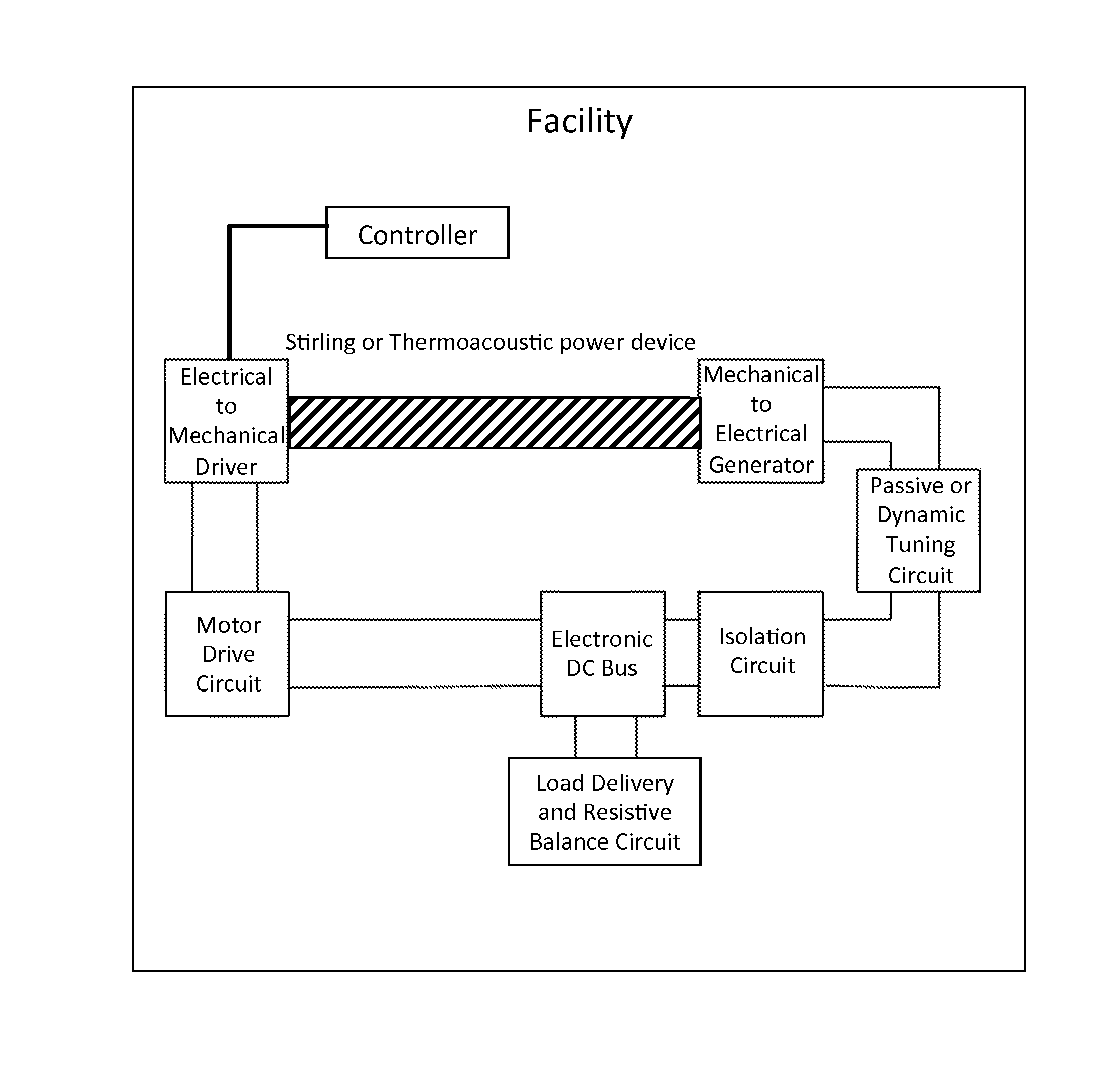
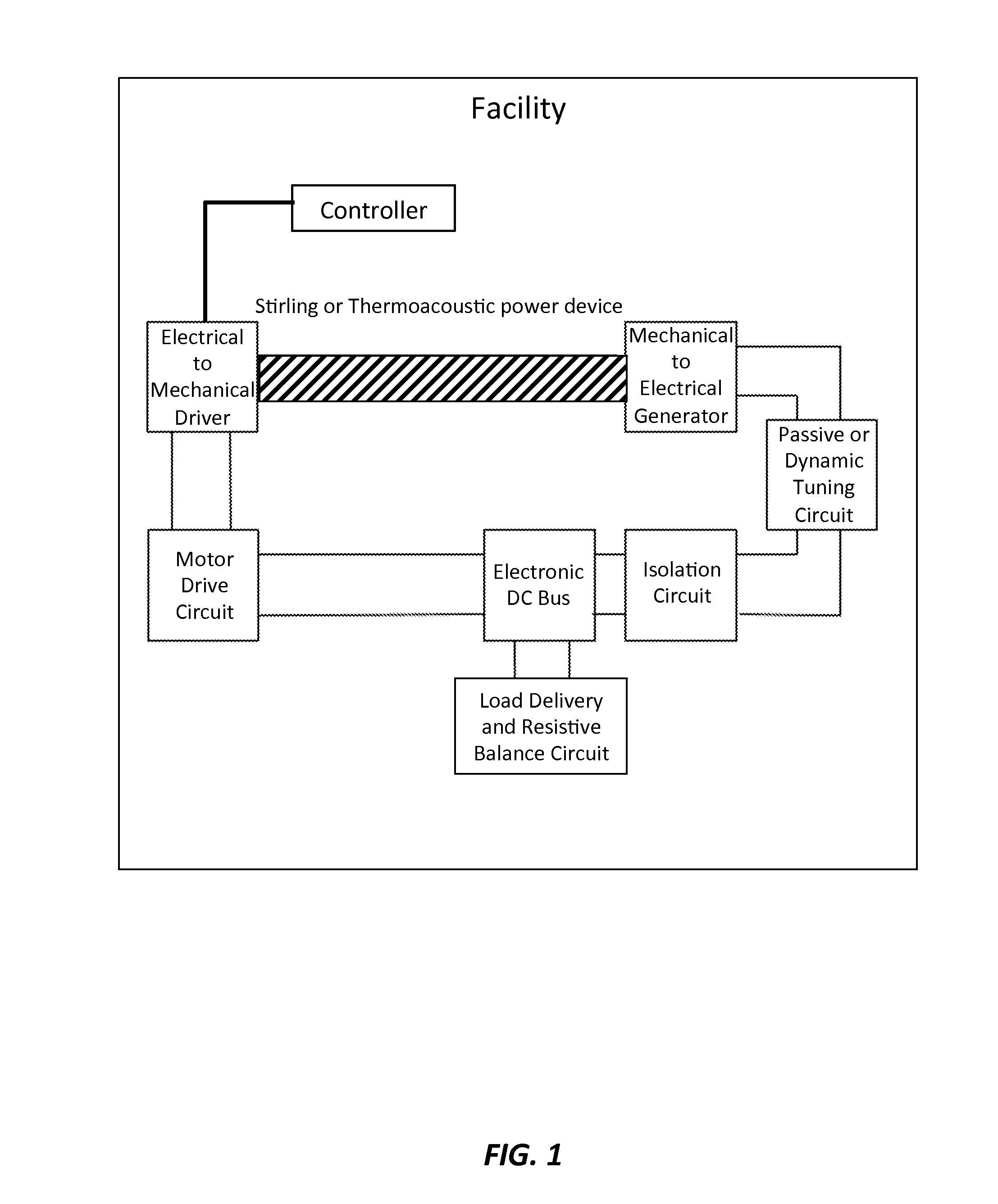
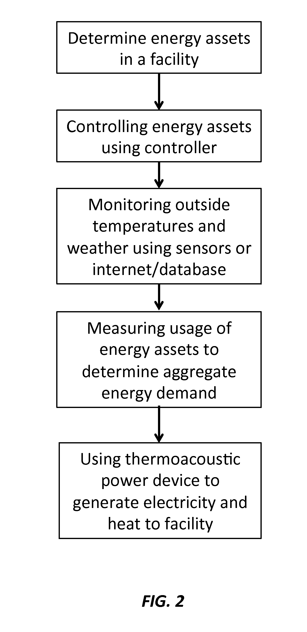
[0027]FIG. 1 and FIG. 2 show a schematic drawing and a flow diagram of a method of controlling facility power requirements using a thermoacoustic power device, respectively, that includes determining energy assets in a building, where power requirements and a unique electrical signature of the energy assets are identified, where the energy assets can include electrical appliances, heating appliances, and cooling appliances. The method further includes controlling the energy assets using an appropriately programmed controller, where the controller controls the energy ass...


PUM


Abstract

A method of controlling facility power requirements using a thermoacoustic power device is provided that includes determining energy assets in a facility, controlling the energy assets using an appropriately programmed controller across a network having a security system protocol, monitoring outside temperatures and weather, measuring usage of the energy assets using a temperature sensor or an electrical usage sensor to a load-response signal of an on / off operation and usage of the energy assets to identify a specific energy asset by the controller to determine aggregate energy needs of the energy assets, and using a thermoacoustic power device controlled by the controller to generate electricity and heat according to the monitored temperature, weather and energy assets.

Description

CROSS-REFERENCE TO RELATED APPLICATIONS[0001]This application claims priority from U.S. Provisional Patent Application 62 / 083,666 filed Nov. 24, 2014, which is incorporated herein by reference. This application claims priority from U.S. Provisional Patent Application 62 / 083,660 filed Nov. 24, 2014, which is incorporated herein by reference. This application claims priority from U.S. Provisional Patent Application 62 / 083,812 filed Nov. 24, 2014, which is incorporated herein by reference. This application claims priority from U.S. Provisional Patent Application 62 / 083,628 filed Nov. 24, 2014, which is incorporated herein by reference. This application claims priority from U.S. Provisional Patent Application 62 / 083,633 filed Nov. 24, 2014, which is incorporated herein by reference. This application claims priority from U.S. Provisional Patent Application 62 / 083,642 filed Nov. 24, 2014, which is incorporated herein by reference. This application claims priority from U.S. Provisional Pat...

Claims


Application Information

Patent Timeline
IPC IPC(8): F02G5/00F02B71/04F02B63/04
CPCF02G5/00F02B63/043F05D2270/14F02G2250/00F02B71/04F02G1/06F02G2243/54F05D2260/962H02K53/00Y02E20/14
Inventor HESSELINK, LAMBERTUSBRUDER, GEOFFREY A.PICKENS, MARK A.BATRA, RAJESHTROY, NEIL W.DYSON, JR., RODGER W.
Owner NIRVANA ENERGY SYST
Learn More