Charging device of a welding fixture of spacer grid

a charging device and welding fixture technology, applied in the direction of electrical welding devices, soldering apparatus, nuclear elements, etc., can solve the problems of the spacer grid itself swaying, and achieve the effects of preventing overload, preventing damage to the welding fixture, and increasing workability and productivity

Active Publication Date: 2016-06-02
KEPCO NUCLEAR FUEL CO LTD
View PDF6 Cites 7 Cited by
  • Summary
  • Abstract
  • Description
  • Claims
  • Application Information

AI Technical Summary

Benefits of technology

[0021]The present invention has the following advantages. The charging device of a welding fixture of spacer grid according to the present invention has the effect to increase workability and productivity by automating charging and withdrawing a welding fixture in a welding chamber, and prevent damage of a welding fixture by preventing overload which can happen to a gripper while withdrawing a welding fixture.
[0022]And also the present invention separates the position of a welding fixture before and after welding into a plurality of positions and a welding fixture before and after welding can be transferred on a single conveyor line in both directions. Thus welding operation can be efficiently achieved.

Problems solved by technology

However these spacer grid straps are interconnected to each other by inserting into incision parts, spacer grid itself sways because of gaps in most incision parts.

Method used


Image

  • Charging device of a welding fixture of spacer grid
  • Charging device of a welding fixture of spacer grid
  • Charging device of a welding fixture of spacer grid

Examples


Embodiment Construction

[0037]Specific configurations or functional descriptions which set forth in exemplary embodiments according to the present invention are only for the purpose of describing exemplary embodiments, and the exemplary embodiments according to the concept of the present invention can be practiced in various forms. Thus the present invention is not limited to the described exemplary embodiments and all of appropriate variations, modifications and equivalents are considered to pertain to the scope of the present invention.

[0038]The terms used in this specification are only for describing the specific exemplary embodiment, not meat to limit the present invention. The singular expression implies both singular and plural meaning unless it is distinctly different by context.

[0039]Specific exemplary embodiment of the present invention will be explained from the following detailed description when taken in conjunction with the accompanying drawings as follows.

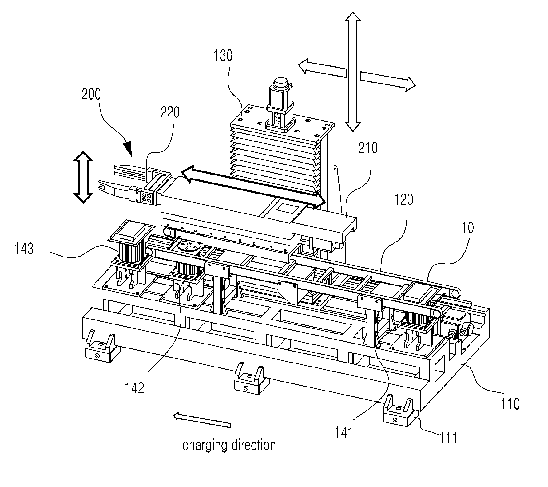
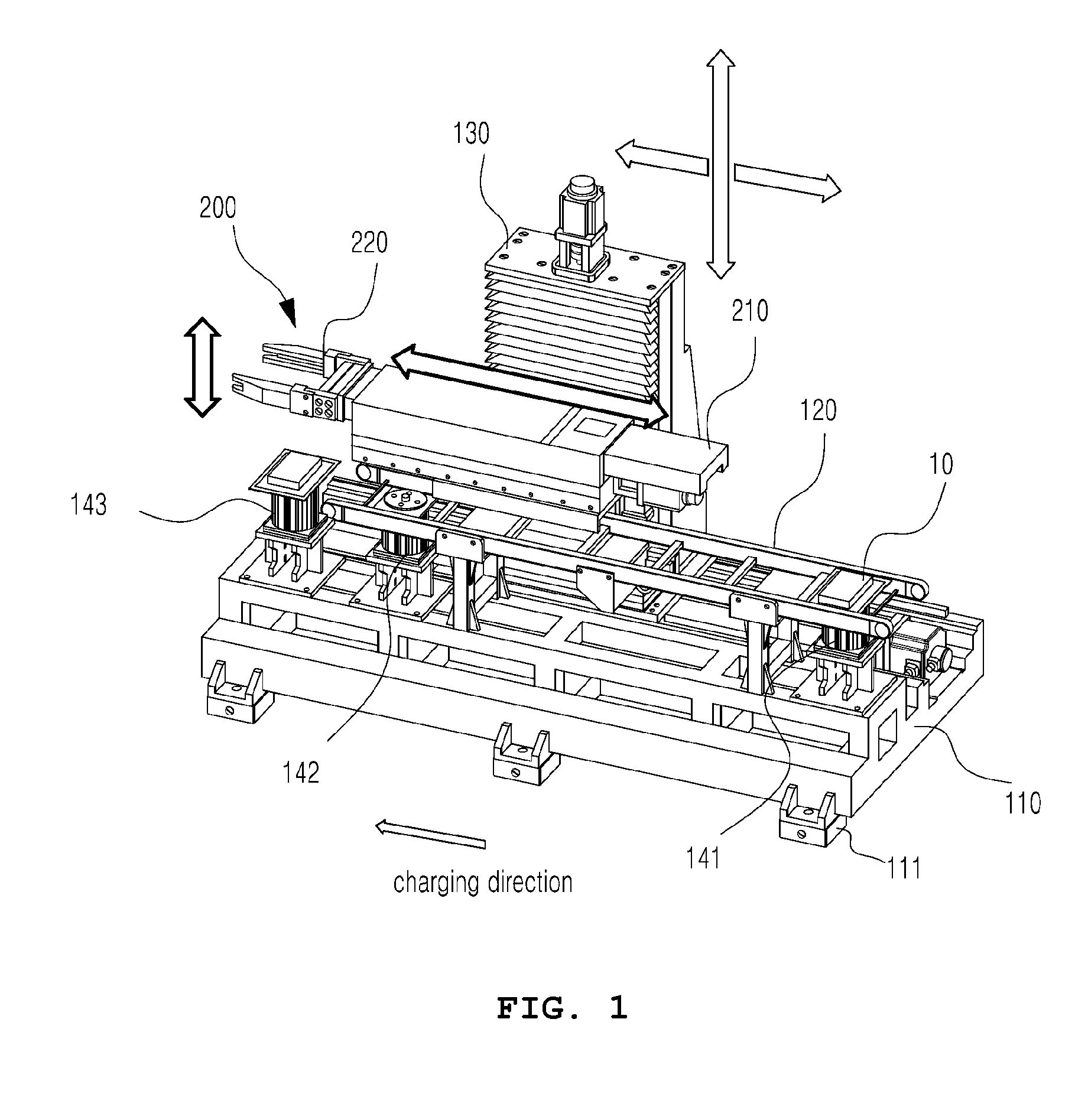
[0040]As illustrated in FIG. 1, a cha...


PUM

PropertyMeasurementUnit
elasticaaaaaaaaaa
widthaaaaaaaaaa
separation distanceaaaaaaaaaa

Abstract

A charging device of a welding fixture of spacer grid comprises a base frame; a conveyor for conveying a welding fixture horizontally over the base frame; and a gripper located over the base frame for gripping a welding fixture conveyed along the conveyor to charge a welding fixture into a welding chamber, wherein the gripper comprises a gripper body; and a gripping part installed horizontal to the end of the gripper body for gripping a welding fixture and capable of tilting in vertical direction to the gripper body in case more than a predetermined load is applied as a vertical load.

Description

BACKGROUND OF THE INVENTION[0001]1. Field of the Invention[0002]The present invention relates to a charging device of a welding fixture of spacer grid.[0003]2. Description of the Related Art[0004]Generally, a nuclear reactor is equipment that is made to control nuclear fission artificially to generate heat, or to be used for various purposes such as production of radioisotope or plutonium, or radiation filed formation, etc.[0005]In general, light water reactor nuclear power plant uses enriched uranium in which ratio of uranium-235 is increased by 2 to 5%. For nuclear fuel to be used in nuclear reactors, fuel fabrication is processed in such a way that cylindrical pellet hefting about 5 g is made of uranium. In order to manufacture a fuel rod, these pellets come charging zircaloy cladding and spring and helium gas are put in and then an end plug is welded in a rod end. The fuel rods are charged in skeleton finally to form a fuel assembly and combusted by nuclear reaction in the nucle...

Claims


Application Information

Patent Timeline
Patent Type & Authority Applications(United States)
IPC IPC(8): B23K26/08B23K37/04
CPCB23K37/0435B23K26/0853B23K37/00B23K37/02B23K31/022B23K2101/22B23Q1/25G21C3/34G21C3/3424
Inventor OH, BYEONG EUNYUN, KWANG HOSHIN, DONG KWANGYANG, HEUI SEOBHAN, SANG JAEHONG, JONG SUNG
Owner KEPCO NUCLEAR FUEL CO LTD
Why Eureka
Try Eureka