
Method for printing a material to be printed

a printing method and material technology, applied in the field of printing a material to be printed, can solve the problems of deformation of printing materials, registration and/or registration that no longer meet quality standards, etc., and achieve the effects of reducing the number of devices and operating steps, saving printing materials, and avoiding unnecessary defects in printed printing images

Active Publication Date: 2016-06-02
KOENIG & BAUER AG
View PDF9 Cites 10 Cited by
  • Summary
  • Abstract
  • Description
  • Claims
  • Application Information

AI Technical Summary

Benefits of technology

The invention relates to a method for printing with inkjet technology. One advantage of this method is that it allows for the removal of unnecessary parts of the printed product after printing, resulting in savings of ink and a reduction in the number of devices and steps required. This is achieved by selectively actuating the nozzles of the print head based on the data in the printing image. Another advantage is that defects in the printed image are avoided. The method also allows for processing and checking of sequential printing images and templates for opportunities to save ink and improve print quality.

Problems solved by technology

Frequently, as the printing material is being transported between the first printing unit and the second printing unit, a deformation of the printing material can occur, for example a shrinkage due to a loss of moisture resulting from an intermediate drying process and / or a stretching resulting from a softening of the printing material by solvent and / or water that is applied along with the coating medium.
This can result in a registration and / or register that no longer meet the standards for quality.

Method used


Image

  • Method for printing a material to be printed
  • Method for printing a material to be printed
  • Method for printing a material to be printed

Examples


Embodiment Construction

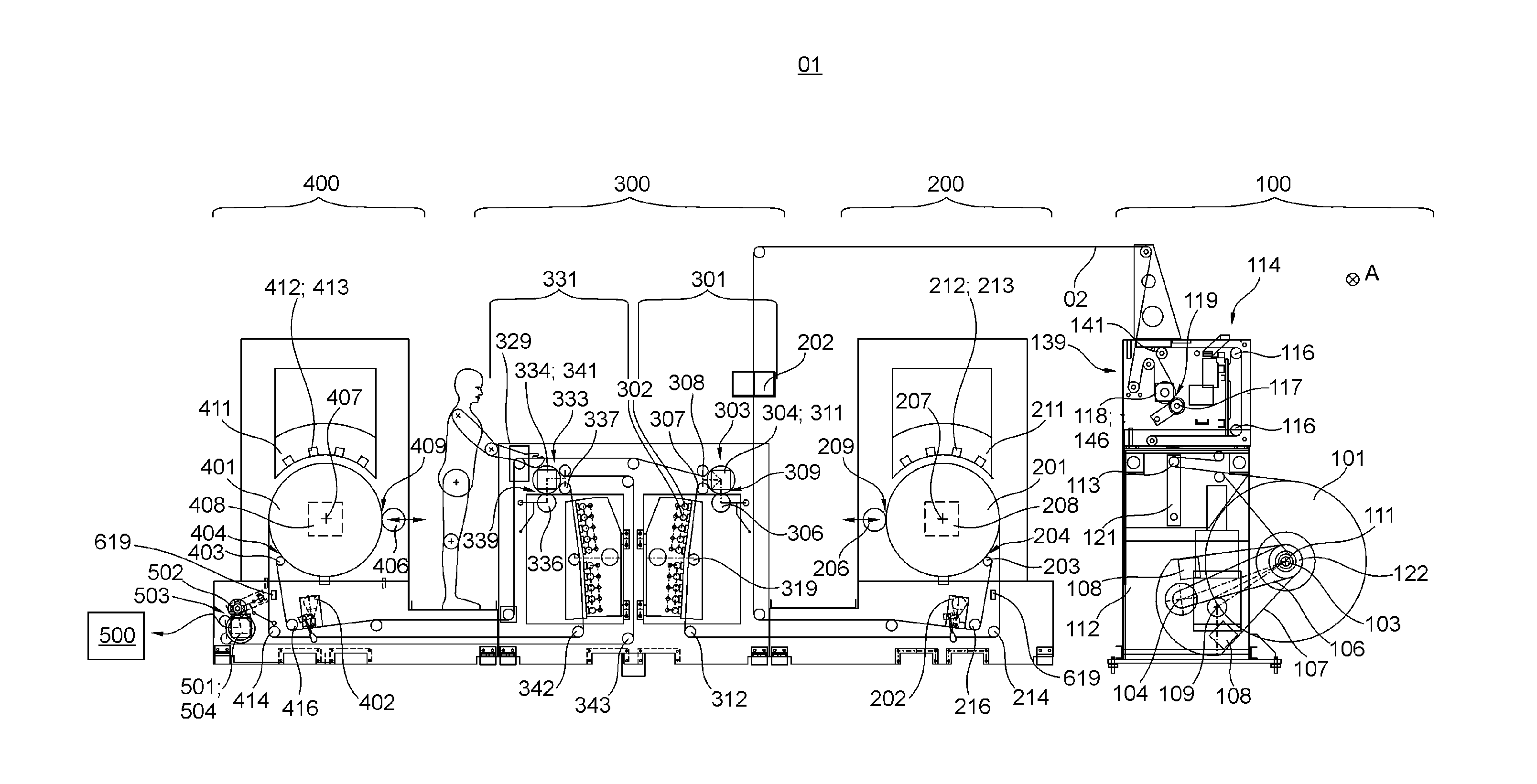
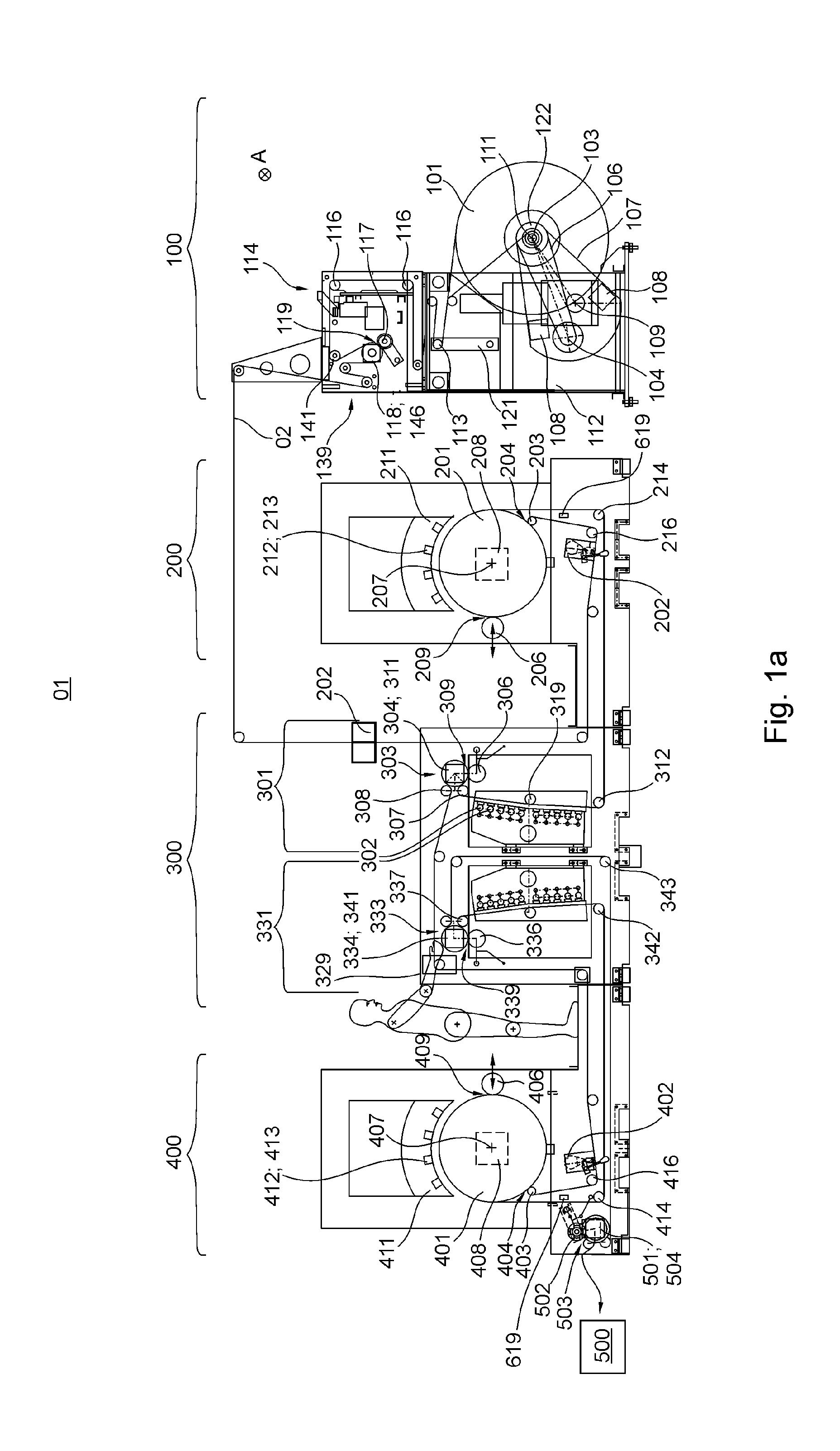
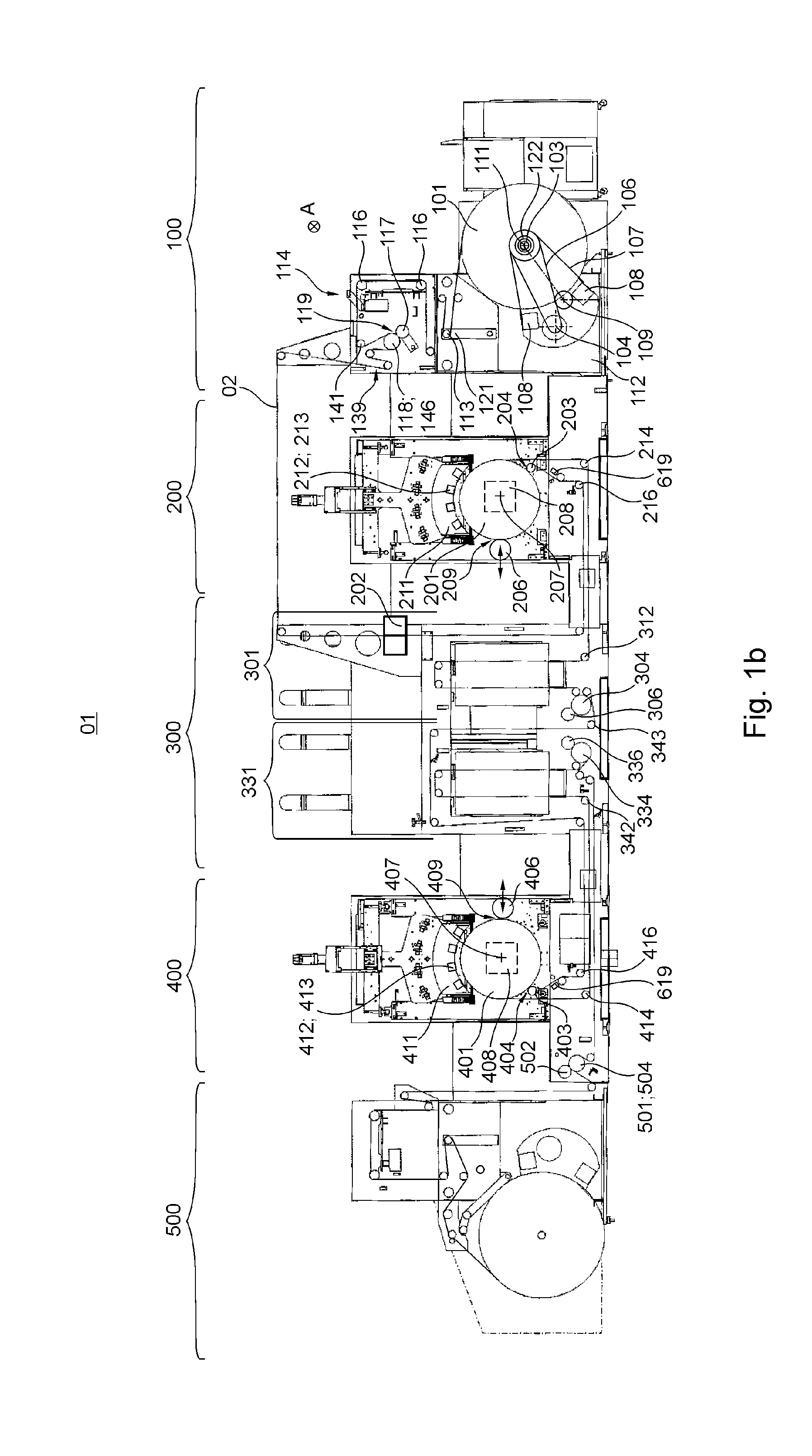
[0102]A printing machine 01 comprises at least one printing material source 100, at least one first printing unit 200, preferably at least one first dryer 301, preferably at least one second printing unit 400 and preferably at least one second dryer 331, and preferably at least one post-processing unit 500. Printing machine 01 is further preferably embodied as an inkjet printing machine 01. Printing machine 01 is preferably embodied as a web-fed printing machine 01, and more preferably as a web-fed inkjet printing machine 01. Printing machine 01 is embodied, for example, as a rotary printing machine 01, for example as a web-fed rotary printing machine 01, in particular a web-fed rotary inkjet printing machine 01. In the case of a web-fed printing machine 01, printing material source 100 is embodied as a roll unwinding device 100. In the case of a sheet-fed printing machine or a sheet-fed rotary printing machine, printing material source 100 is embodied as a sheet feeder. In printing...


PUM


Abstract

A method for printing a strip-shaped material to be printed uses a printing unit of a roller printer. Output data for actuating at least one printing machine printing unit component, which determines the shape of printing images, is generated from stored template image data of a complete printing image in order to generate a printed complete printing image. The complete printing image is determined or described in a primary data packet, and the dimensions of the complete image, which dimensions are measured in a template direction, are assigned to the complete printing image in the template image data or the primary data packet. The dimensions of the complete image are compared with a threshold, and if the threshold is exceeded, the complete printing image is divided into a plurality of sections with respect to the template direction, with the plurality of sections being determined or described in a plurality of secondary data packets. The sections are produced on the material to be printed by printing processes which are carried out by the printing unit and during each of which, output data, based on at least one of the secondary data packets, is processed.

Description

CROSS-REFERENCE TO RELATED APPLICATIONS[0001]This application is the U.S. National Phase, under 35 U.S.C. §371, of PCT / EP2014 / 065214, filed Jul. 16, 2014, published as WO 2015 / 007764A1 on Jan. 22, 2015 and claiming priority to DE 10 2013 214 025.8, filed Jul. 17, 2013, the disclosures of which are expressly incorporated herein by reference.FIELD OF THE INVENTION[0002]The invention relates to a method for printing a material to be printed.BACKGROUND OF THE INVENTION[0003]A variety of different printing methods for use in printing machines are known. Such printing methods include, for example, printing methods that do not involve a fixed printing forme. This enables each printed product to be produced individually. As a result, personalized printed products can be produced and / or, since printing formes are dispensed with, small print runs of printed products can be produced at low cost. Once such printing method is inkjet printing or ink-jet printing. In this method, individual drople...

Claims


Application Information

Patent Timeline
Patent Type & Authority Applications(United States)
IPC IPC(8): G06K15/02G06K15/10
CPCG06K15/022G06K15/1843G06K15/102G06K15/1863G06K15/1896B41F19/007B41J3/60B41J11/008B41J2/2132B41J2/2146
Inventor BLANK, ALEXANDERHUPPMANN, FRANKJANK, CHRISTIAN
Owner KOENIG & BAUER AG
Learn More