
Semiconductor device, method for manufacturing semiconductor device, module, and electronic device
a semiconductor and semiconductor technology, applied in the direction of semiconductor devices, electrical devices, transistors, etc., can solve the problems of small power consumption of display devices in which a transistor including an oxide semiconductor is used, and achieve the effects of stable electrical characteristics, excellent electrical characteristics, and low leakage curren
- Summary
- Abstract
- Description
- Claims
- Application Information
AI Technical Summary
Benefits of technology
Problems solved by technology
Method used
Image

Examples
embodiment 1
[0100]In this embodiment, an example of a transistor of one embodiment of the present invention will be described.
1>
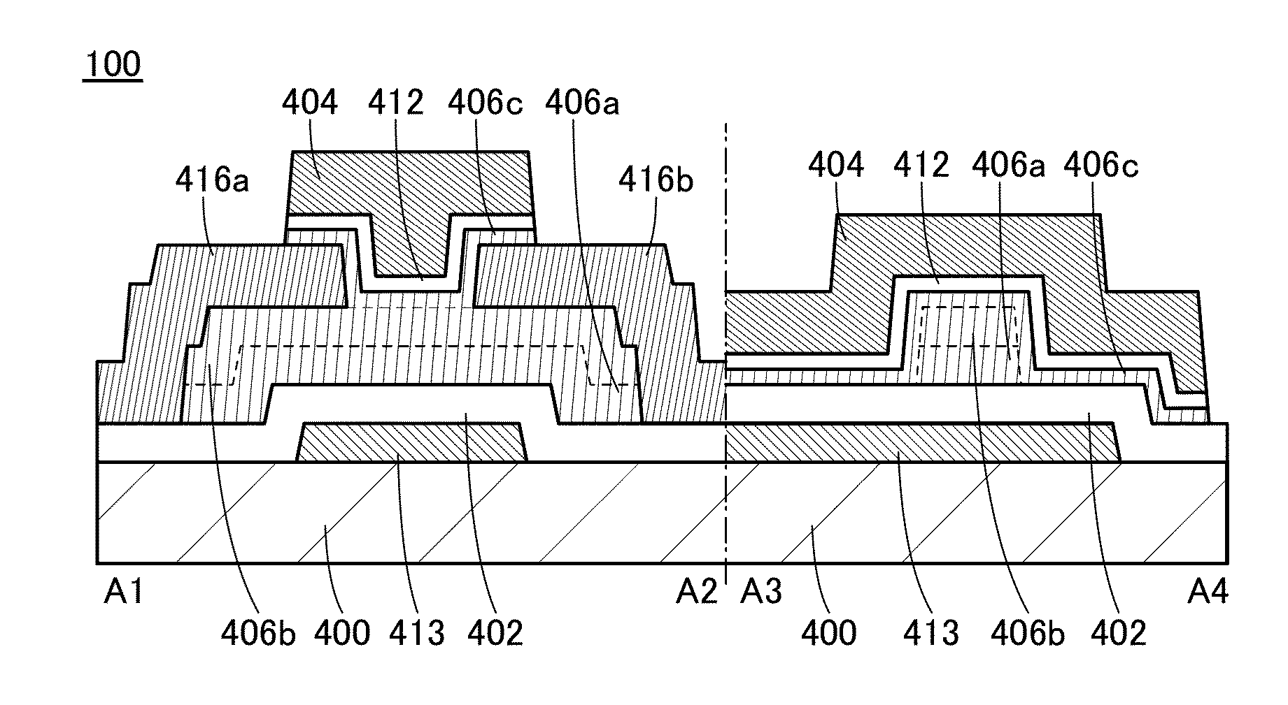
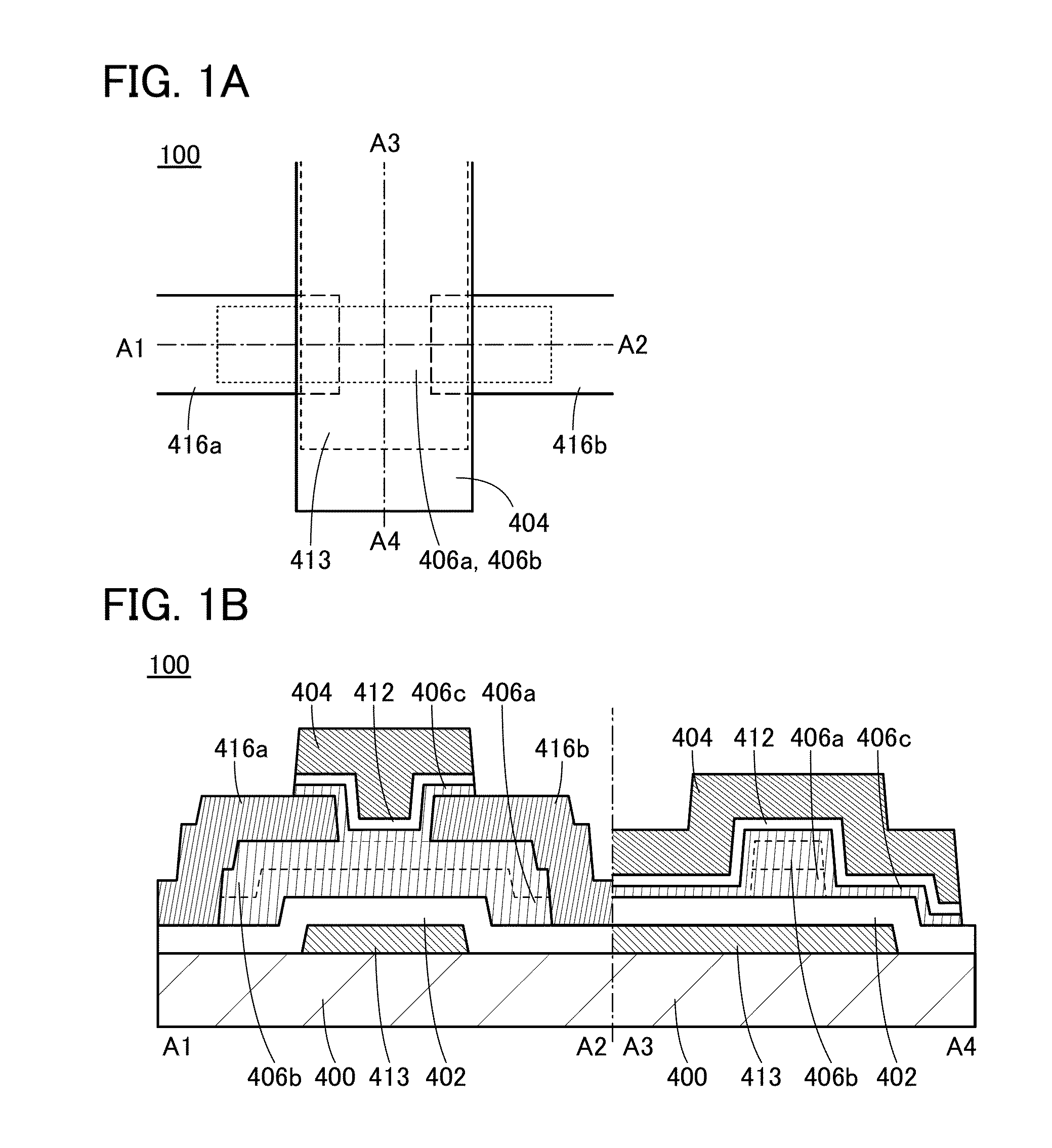
[0101]FIGS. 1A and 1B illustrate a transistor of one embodiment of the present invention. FIG. 1A is a top view of a transistor 100, and FIG. 1B is a cross-sectional view taken along dashed-dotted lines A1-A2 and A3-A4 in FIG. 1A. The transistor 100 includes a substrate 400, a conductor 413, an insulator 402, a semiconductor 406a, a semiconductor 406b, a semiconductor 406c, a conductor 416a, a conductor 416b, an insulator 412, and a conductor 404.
[0102]The semiconductors 406a, 406b, or 406c of the transistor 100 can contain fluorine. All of the three layers may contain fluorine. Alternatively, any one or two of the three layers may contain fluorine.
[0103]In the case where a semiconductor of a transistor includes a plurality of layers as described in this embodiment, a semiconductor including a channel formation region preferably contains fluorine. For example, in the c...
embodiment 2
[0228]In this embodiment, a method for manufacturing a transistor whose shape is partly different from that of the transistor in Embodiment 1 is described.
2>
[0229]FIG. 15A, FIG. 16A, FIG. 17A, FIG. 18A, FIG. 19A, FIG. 20A, and FIG. 21A are top views illustrating a method for manufacturing a transistor. FIG. 15B, FIG. 16B, FIG. 17B, FIG. 18B, FIG. 19B, FIG. 20B, and FIG. 21B are each a cross-sectional view taken along dashed dotted lines F1-F2 and F3-F4 shown in the corresponding top view.
[0230]First, a substrate 500 is prepared. For the substrate 500, the description of the substrate 400 is referred to.
[0231]Next, a conductor is formed. The conductor may be formed by a sputtering method, a CVD method, an MBE method, a PLD method, an ALD method, or the like.
[0232]Next, a resist or the like is formed over the conductor and the conductor is processed into a conductor 513 using the resist.
[0233]Next, an insulator is formed. The insulator can be formed by a sputtering method, a CVD metho...
embodiment 3
[0266]In this embodiment, an example of a circuit of a semiconductor device including a transistor or the like of one embodiment of the present invention is described.
[0267]A circuit diagram in FIG. 24A illustrates a configuration of a so-called CMOS inverter in which a p-channel transistor 2200 and an n-channel transistor 2100 are connected to each other in series and gates of them are connected to each other. It is preferable that a transistor including an oxide semiconductor be used as the n-channel transistor 2100. Thus, power consumption of the CMOS inverter circuit can be reduced.
[0268]A circuit diagram in FIG. 24B illustrates a configuration in which sources of the transistors 2100 and 2200 are connected to each other and drains of the transistors 2100 and 2200 are connected to each other. With such a configuration, the transistors can function as a so-called CMOS analog switch. It is preferable that a transistor including an oxide semiconductor be used as the n-channel trans...
PUM
 Abstract
Description
Claims
Application Information