Magnetic etch stop layer for spin-transfer torque magnetoresistive random access memory magnetic tunnel junction device

a technology of magnetic tunnel junction and stop layer, which is applied in the direction of magnetic field-controlled resistors, semiconductor devices, electrical devices, etc., can solve the problems of significant degradation and damage to the magnetic properties of the free layer

Inactive Publication Date: 2016-06-02
QUALCOMM INC
View PDF5 Cites 29 Cited by
  • Summary
  • Abstract
  • Description
  • Claims
  • Application Information

AI Technical Summary

Benefits of technology

[0005]The capping layer above the free layer may be comprised of Magnesium Oxide (MgO), Aluminum Oxide (AlOx), Hafnium Oxide (HfOx), or Tantalum Oxide (TaOx) and the magnetic etch stop layer may be comprised of Cobalt Iron Boron (CoFeB), Cobalt Iron (CoFe), Iron Boron (FeB), Cobalt Iron (CoFe), Nickel Iron Boron (NiFeB), Nickel Iron Silicon Boron (NiFeSiB), or Nickel Iron (NiFe). The magnetic etch stop layer may be deposited on top of the capping layer to protect both layers during etching. For example, a hard mask may be placed on the top electrode (located on top of the magnetic etch stop layer), and the MTJ device may undergo an etching process. During the etching process, t

Problems solved by technology

During fabrication, magnetic properties of the free layer may be damaged during etching of adjacent layers (e.g., during etching of a capping layer).
Sacrificial etch stop layers (or buffer layers) may be dep

Method used


Image

  • Magnetic etch stop layer for spin-transfer torque magnetoresistive random access memory magnetic tunnel junction device
  • Magnetic etch stop layer for spin-transfer torque magnetoresistive random access memory magnetic tunnel junction device
  • Magnetic etch stop layer for spin-transfer torque magnetoresistive random access memory magnetic tunnel junction device

Examples


first embodiment

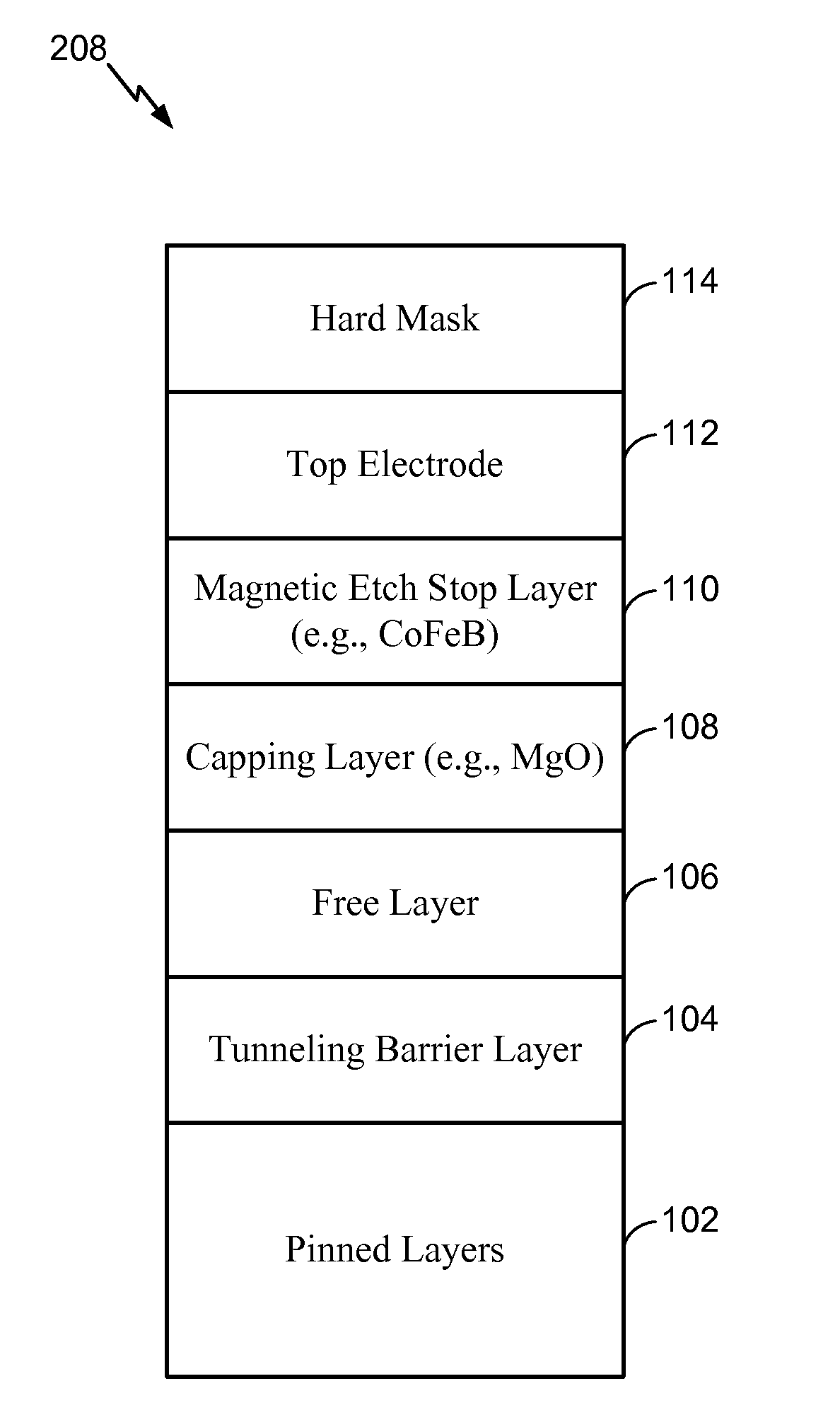
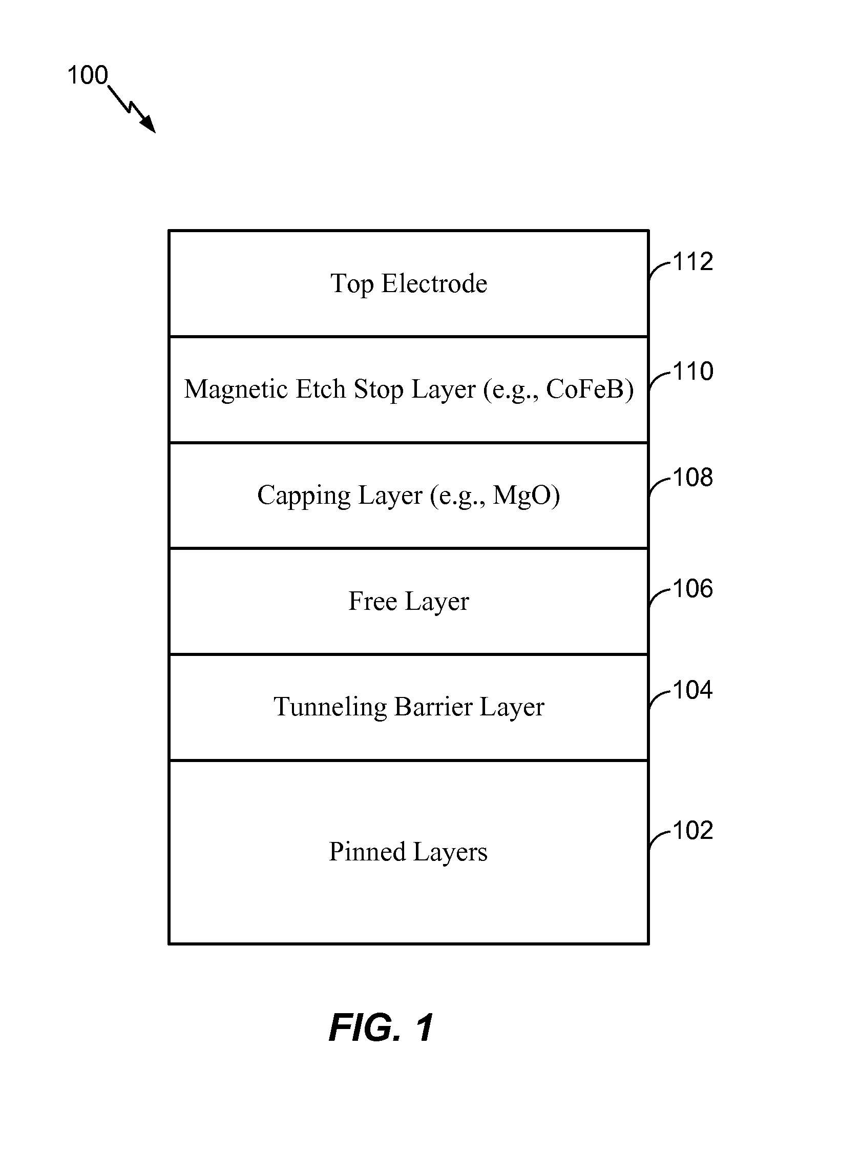
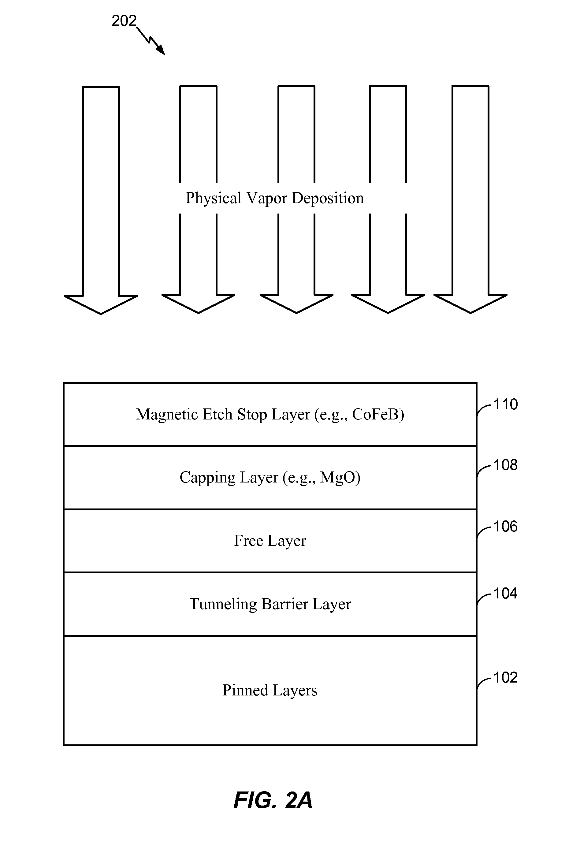
[0027]In a first embodiment, the magnetic etch stop layer 110 may be sufficiently thin as to operate as a “magnetically dead” layer. For example, a thickness of the magnetic etch stop layer 110 may cause the magnetic etch stop layer 110 to be substantially magnetically inert. As a non-limiting illustrative example, the thickness of the magnetic etch stop layer 110 may be approximately 5 Angstroms or less such that the magnetic etch stop layer 110 is substantially magnetically inert. When the magnetic etch stop layer 110 is magnetically inert, the magnetic contribution of the magnetic etch stop layer 110 to the STT-MRAM MTJ device 100 may be significantly reduced (or may be non-existent). For example, using a “thin” Cobalt Iron Boron (CoFeB) layer on top of a Magnesium Oxide (MgO) capping layer may enhance performance of the STT-MRAM MTJ device 100 by aiding in the formation of high perpendicular magnetic anisotropy in the free layer while protecting the free layer 106 during reactiv...

second embodiment

[0028]In a second embodiment, the thickness of the magnetic etch stop layer 110 may cause the magnetic etch stop layer 110 to introduce in-plane anisotropy (e.g., exhibit magnetic moments) to the STT-MRAM MTJ device 100. As a non-limiting example, the thickness of the magnetic etch stop layer 110 may be between approximately 10 Angstroms and 30 Angstroms. The in-plane anisotropy (as opposed to a perpendicular anisotropy having a magnetic moment oriented out of the plane (e.g., vertically) of the STT-MRAM MTJ device 100) may reduce the switching current density (or energy) needed to operate the STT-MRAM MTJ device 100 without degrading tunnel magneto-resistance (TMR) and thermal barrier of the STT-MRAM MTJ device 100. For example, the magnetic etch stop layer 110 may be “weakly” coupled to the free layer 106 by ferromagnetic coupling. The free layer 106 may have a perpendicular anisotropy (e.g., a magnetic moment oriented in a vertical direction) and the magnetic etch stop layer 110 ...


PUM


Abstract

An apparatus includes a capping layer disposed on top of a free layer. The apparatus also includes a magnetic etch stop layer disposed on top of the capping layer. The capping layer and the magnetic etch stop layer are included in a spin-transfer torque magnetoresistive random access memory (STT-MRAM) magnetic tunnel junction (MTJ) device.

Description

I. FIELD[0001]The present disclosure is generally related to a magnetic etch stop layer for a spin-transfer torque magnetoresistive random access memory (STT-MRAM) magnetic tunnel junction (MTJ) device.II. DESCRIPTION OF RELATED ART[0002]Advances in technology have resulted in smaller and more powerful computing devices. For example, there currently exist a variety of portable personal computing devices, including wireless telephones such as mobile and smart phones, tablets, and laptop computers that are small, lightweight, and easily carried by users. These devices can communicate voice and data packets over wireless networks. Further, many such devices incorporate additional functionality such as a digital still camera, a digital video camera, a digital recorder, and an audio file player. Also, such devices can process executable instructions, including software applications, such as a web browser application, that can be used to access the Internet. As such, these devices can inc...

Claims


Application Information

Patent Timeline
IPC IPC(8): H01L43/08H01L43/12H01L43/02
CPCH01L43/08H01L43/12H01L43/02H10N50/10H10N50/01
Inventor LEE, KANGHOPARK, CHANDOKAN, JIMMYGOTTWALD, MATTHIAS GEORGZHU, XIAOCHUNKANG, SEUNG HYUK
Owner QUALCOMM INC
Why Eureka
Try Eureka