Radio frequency identification (RFID) devices for detecting volatile substances

Active Publication Date: 2016-06-09
YAN NING
21 Cites 6 Cited by

AI-Extracted Technical Summary

Problems solved by technology

However, unlike RFID tags, electronic noses are large, costly, require a power source, and cannot be easily integrated into packaging.
Amine identification and quantification is challenging because underivatized amines are difficult to separate in common liquid and gas chromatography columns.
Traditional analytical techniques such as gas chromatography coupled to mass spectrometry are not desirable because samples containing multiple amines must be derivatized to be sufficiently separated.
In addition, this technique is costly, time consuming and requires a trained tec...

Benefits of technology

[0051]In another embodiment, the RFID device of the present invention may exhibit an “on” or an “off” state. Preferably when exposed to an environment having an increasing concentration of a volatile su...

Abstract

A radio frequency identification device, for detecting at least one volatile substance, comprising an integrated circuit, an antenna electrically connected to said integrated circuit, and at least one conductor, between said integrated circuit and said antenna, preferably said at least one conductor comprises a conducting composite, preferably said conducting composite comprises a polymer matrix and a conductor.

Application Domain

Resistance/reactance/impedenceMaterial resistance

Technology Topic

Radio frequencyIntegrated circuit +3

Image

  • Radio frequency identification (RFID) devices for detecting volatile substances
  • Radio frequency identification (RFID) devices for detecting volatile substances
  • Radio frequency identification (RFID) devices for detecting volatile substances

Examples

  • Experimental program(17)

Example

Example 1
[0090]The conducting composite was integrated onto the RFID device between the device's integrated circuit and antenna. A solution of 18 weight % carbon and 82 weight % polymer (see Table 1) was prepared for a total of 0.1 g in 15 mL of water, chloroform, or THF depending on the solubility of the polymer. The solution was sonicated for 3 h at room temperature. The unmodified RFID devices were received as a copper antenna sandwiched between two plastic sheets. The top plastic sheet was removed and the copper antenna was cleaned with acetone to remove any adhesive. The silver conductive paste that runs between the tag's integrated circuit and the antenna was modified with the conductive composite. First, the area was masked off by applying the silicone elastomer to the area identified above and curing for 2 h at 70° C. Once cured, the silicone was cut so that only the area with the conductive paste was exposed, and the remaining area was masked off with the silicone elastomer. Second, 10 μL of the conductive composite solution was pipetted onto the masked area and heated to 80° C. for 10 minutes to evaporate the solvent, leaving behind the conductive composite film. Modified RFID device resistance was measured with a digital multimeter (Mastercraft) and was found to increase from 1.2Ω to 3.0Ω upon addition of the first layer of conductive composite. Multiple layers of conductive composite were added to the tag to make tags with resistance 4.2, 7.5, 10.5, and 12.8Ω. All experiments were performed using tags with a resistance 10.5±0.5Ω unless stated otherwise. The resistance of RFID tag sensors is much lower than the resistance of electronic nose devices made from conducting polymer composites, which is typically on the order of MΩ. RFID tag devices operate at low resistance because the tags need to reach a critical DC voltage for microchip operation. Electronic noses made from conducting polymer composites operate at a high resistance to work near the percolation threshold to achieve the largest changes in resistance. After modification, the operating frequency of the RFID tags was found to increase from 13.56 MHz to 14.2 MHz.

Example

Example 2
[0091]A solution of 18 weight % carbon black, 50 weight % PEVA and 32 weight % maleic acid was prepared for a total of 0.15 g in 15 mL of chlorobenzene. The solution was heated for 1 h in a 70° C. oven then sonicated for 1 h at room temperature. The unmodified RFID devices were received as a copper antenna sandwiched between two plastic sheets. The top plastic sheet was removed and the copper antenna was cleaned with acetone to remove any adhesive. The silver conductive paste that runs between the tag's integrated circuit and the antenna was modified with the conductive composite. First, the area was masked off by applying the silicone elastomer to the area identified above and curing for 2 hours at 70° C. Once cured the silicone was cut so that only the area with the conductive paste was exposed and the remaining area was masked off with the silicone elastomer. Second, 10 μL of the conductive composite solution was pipetted onto the masked area and heated to 80° C. for 10 minutes to evaporate the chlorobenzene. Modified RFID device resistance was measured with a digital multimeter and was found to increase from 1.2Ω to 3.0Ω upon addition of the first layer of conductive composite. Multiple layers of conductive composite were added to the device to make modified RFID devices with resistance 4.2, 7.5, 10.5, and 12.8Ω. All experiments were performed using modified RFID devices with a resistance 10.5±0.5Ω unless stated otherwise. After modification the optimal operating frequency of the RFID tags was found to increase from 13.56 MHz to 14.2 MHz.

Example

Example 3
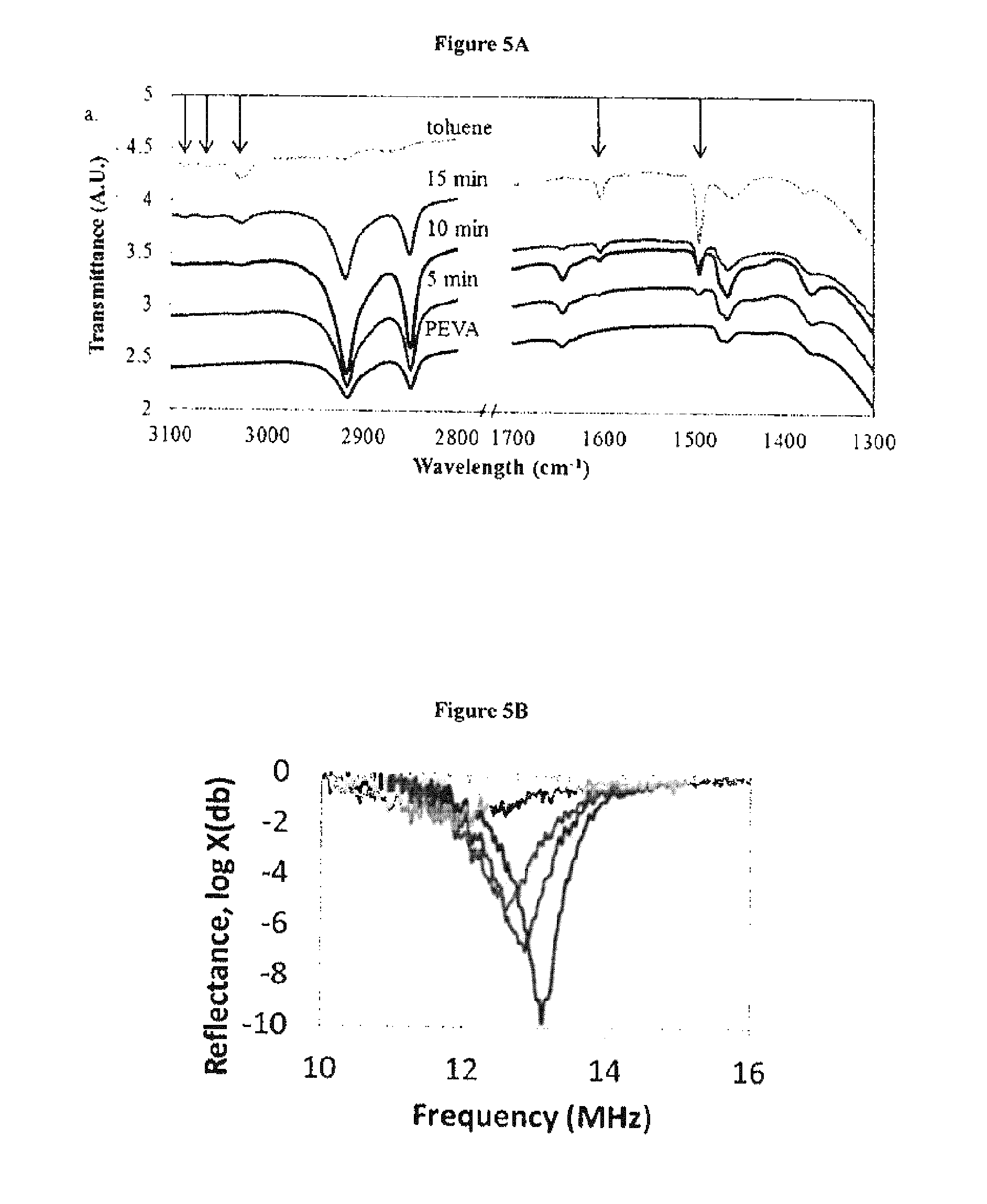
[0092]Conductive composite films were characterized on an attenuated total reflection (ATR) FTIR apparatus. Films of PEVA were cast on silicon wafers. The films were then attached to the inside lid of the environmental chamber and exposed to 377 ppm toluene for 15 minutes. ATR-FTIR measurements were conducted using a single reflection Ge ATR crystal accessory (PIKE Tech.) attached to a Vertex 70 FTIR spectrometer (Bruker Inc.) as described previously (J. Greenerm B. Abbasim E. Kumacheva, Lab on a chip 2010, 10, 1561). Spectra were obtained for the films before exposure, after 5, 10, and 15 min of exposure to toluene and for liquid toluene. FIG. 5A shows the FTIR spectra obtained. Peaks at 3094, 3071, and 3034 cm−1 are C—H stretching for aromatic toluene. Peaks at 1607, and 1503 cm−1 are C—C stretching for aromatic toluene. These aforementioned peaks are not in the PEVA spectrum but are shown to appear as the film is exposed to toluene confirming the analyte adsorption to the film.

PUM

no PUM

Description & Claims & Application Information

We can also present the details of the Description, Claims and Application information to help users get a comprehensive understanding of the technical details of the patent, such as background art, summary of invention, brief description of drawings, description of embodiments, and other original content. On the other hand, users can also determine the specific scope of protection of the technology through the list of claims; as well as understand the changes in the life cycle of the technology with the presentation of the patent timeline. Login to view more.
Why Eureka
Try Eureka