Naturally aspirated common rail diesel engine meeting ultra low pm emission by passive exhaust after treatment

a common rail diesel engine and passive exhaust technology, applied in the direction of electric control, machines/engines, mechanical equipment, etc., can solve the problems of slowing down the chemical reaction of the combustion process, undesirable presence of the latter material in the products, and lowering the maximum combustion temperature within the cylinder, so as to reduce the emission of diesel fuel in the field, reduce the effect of emissions, and improve the efficiency of combustion

Inactive Publication Date: 2016-06-16
MAHINDRA & MAHINDRA LTD
View PDF15 Cites 1 Cited by
  • Summary
  • Abstract
  • Description
  • Claims
  • Application Information

AI Technical Summary

Benefits of technology

[0008]A further object of the invention is to provide an emission control system which will optimize field fuel consumption with good drivability while concurrently minimizing emissions such as nitrous oxide and minimizing the release of undesirable particulate matter.

Problems solved by technology

Since the catalysts employed also had a capability of promoting reduction reactions, there may have occurred during the treatment some reduction of nitrogen oxides into nitrogen and / or ammonia, although the presence of the latter material in the products is undesirable.
This exhaust gas thus reintroduced to the engine cylinder reduces the concentration of oxygen therein, which in turn lowers the maximum combustion temperature within the cylinder and slows the chemical reaction of the combustion process, decreasing the formation of nitrous oxide.
Such, systems are expensive and, therefore, undesirable, particularly where the amount of space available for containing the catalytic equipment is limited as is usually the case with Off-Highway Vehicles.

Method used


Image

  • Naturally aspirated common rail diesel engine meeting ultra low pm emission by passive exhaust after treatment
  • Naturally aspirated common rail diesel engine meeting ultra low pm emission by passive exhaust after treatment
  • Naturally aspirated common rail diesel engine meeting ultra low pm emission by passive exhaust after treatment

Examples


Embodiment Construction

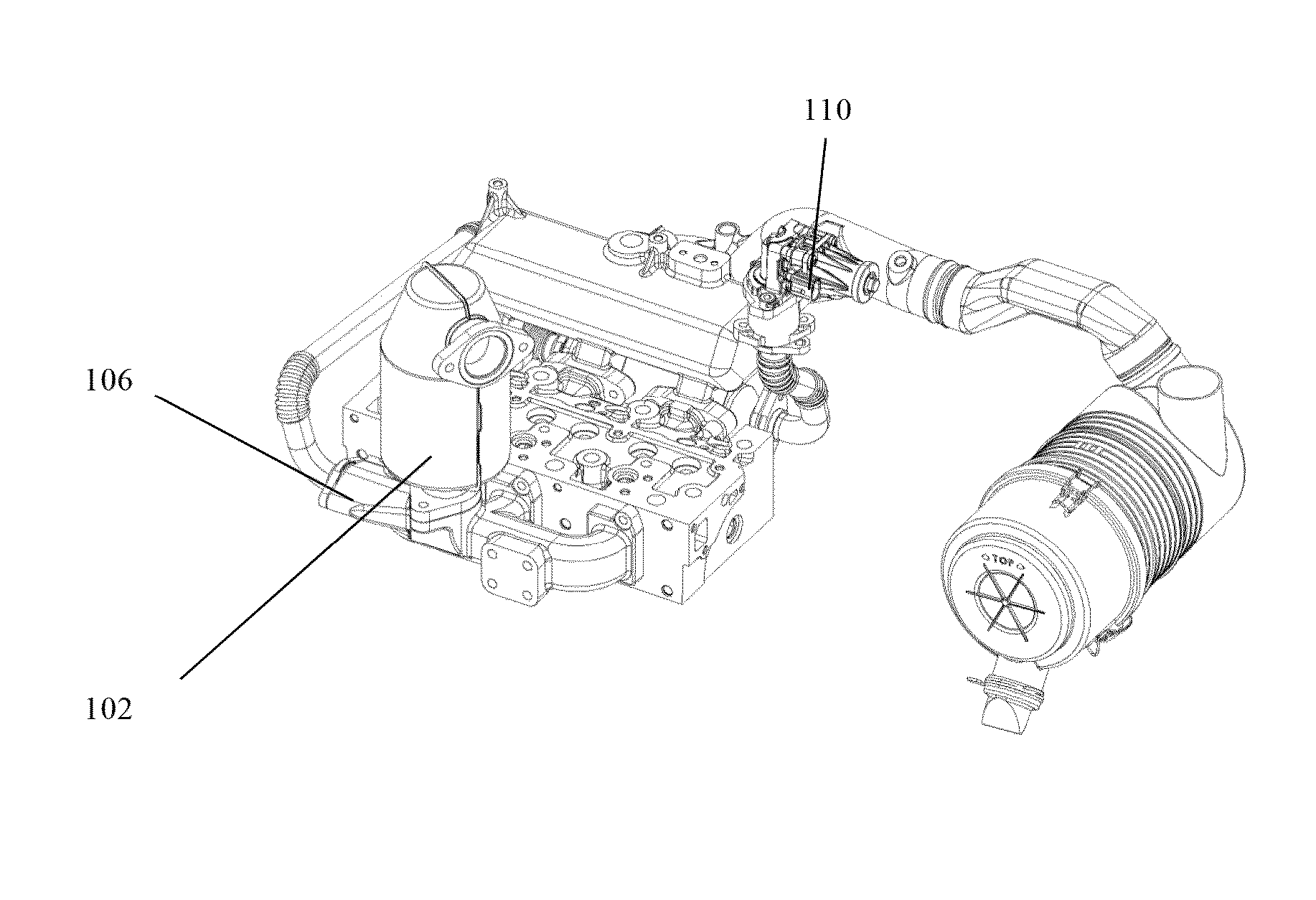
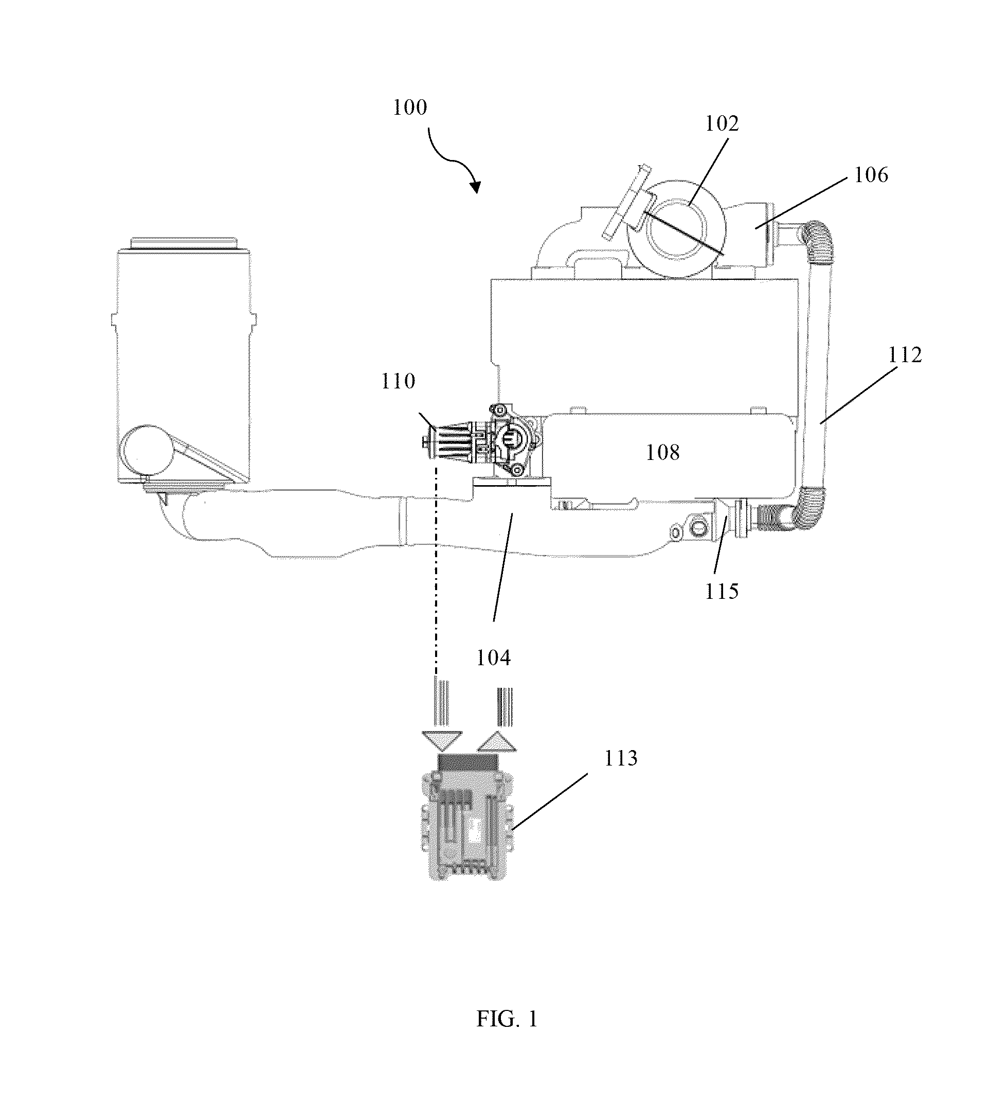
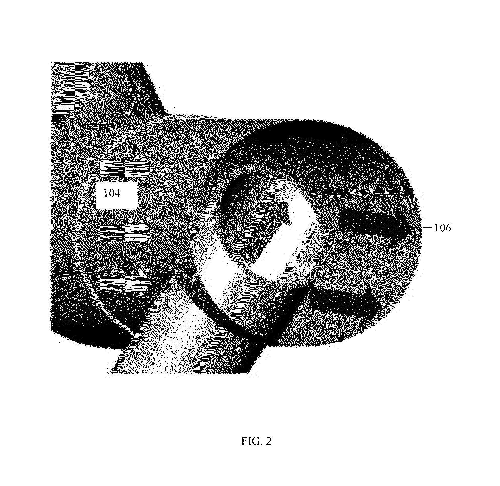
[0018]The embodiments herein and the various features and advantageous details thereof are explained more fully with reference to the non-limiting embodiments that are illustrated in the accompanying drawings and detailed in the following description. Descriptions of well-known components and processing techniques are omitted so as to not unnecessarily obscure the embodiments herein. The examples used herein are intended merely to facilitate an understanding of ways in which the embodiments herein may be practiced and to further enable those of skill in the art to practice the embodiments herein. For example, it should be noted that while some embodiments are explained with respect to a system for controlling emissions of naturally aspirated engine using a catalyst, any other engine may also incorporate the subject matter of the invention with little or no modifications. Accordingly, the examples should not be construed as limiting the scope of the embodiments herein.

[0019]The embod...


PUM


Abstract

A system (100) for controlling emissions of exhaust gases in said naturally aspirated engine is disclosed. The system includes an open loop exhaust gas recirculation flow. The system (100) further includes a catalyst (102) mounted at exhaust manifold (106) of the engine. Furthermore the system (100) includes an exhaust gas mixing tube inserted into intake elbow (104) (mixing tube). The system (100) further includes an exhaust gas recirculation valve (110) mounted on cold side of EGR cooler. Furthermore, the system (100) includes an electronic control unit to control exhaust gas recirculation valve (110) along with various other engine calibration parameters.

Description

CROSS REFERENCES TO RELATED APPLICATIONS[0001]The present application is a national phase application of international application number. PCT / IN2014 / 000486, filed on 23 Jul. 2014 which claims priority from, IN Application Number 3271 / CHE / 2013 filed on 23 Jul. 2013, the disclosure of which is hereby incorporated by reference herein.FIELD OF INVENTION[0002]The embodiments herein relate to emission control system for an internal combustion engine, and more particularly, to method and system for internal combustion engines which will minimize NOx and other emissions while minimizing particulate matter emissions from internal combustion engines.BACKGROUND OF INVENTION[0003]The catalytic treatment of various gaseous streams containing minor amounts of materials which are considered to be atmospheric pollutants such as hydrocarbons, carbon monoxide and nitrogen oxides has been practiced on a commercial basis for a number of years. It is desired to convert these pollutants to the less noxi...

Claims


Application Information

Patent Timeline
Patent Type & Authority Applications(United States)
IPC IPC(8): F02M26/15F01N3/20F02M26/19F01N3/10
CPCF02M26/15F02M26/19F01N3/20F01N3/10F01N13/10F01N2340/02F02D21/08F02D41/0077F02D41/029F02D2200/021F02D2200/0404F02D2200/703F02M26/29Y02T10/40
Inventor VELUSAMY, RRAY, DIPANKARSADANAND, BHOSALEPRAVESH, HIRANANDANISANTOSH, RANESURESH, RATMARAM, DALVIDEEPAK, S
Owner MAHINDRA & MAHINDRA LTD
Why Eureka
Try Eureka