Method and apparatus of detecting states of battery

a battery and state detection technology, applied in the field of battery state detection technology, can solve the problems of battery aging abounding, ages with cumulative working hours and mileage, and fails to meet the need for quick real-time diagnosis

a battery and state detection technology, applied in the field of battery state detection technology, can solve the problems of battery aging abounding, ages with cumulative working hours and mileage, and fails to meet the need for quick real-time diagnosis

US20160178706A1Inactive Publication Date: 2016-06-23NAT CHUNG SHAN INST SCI & TECH

Image

  • Method and apparatus of detecting states of battery
  • Method and apparatus of detecting states of battery
  • Method and apparatus of detecting states of battery

Examples


Embodiment Construction

[0030]The implementation of the present invention is hereunder illustrated with specific embodiments. Persons skilled in the art can easily understand the other advantages and effects of the present invention by referring to the disclosure contained in this specification.

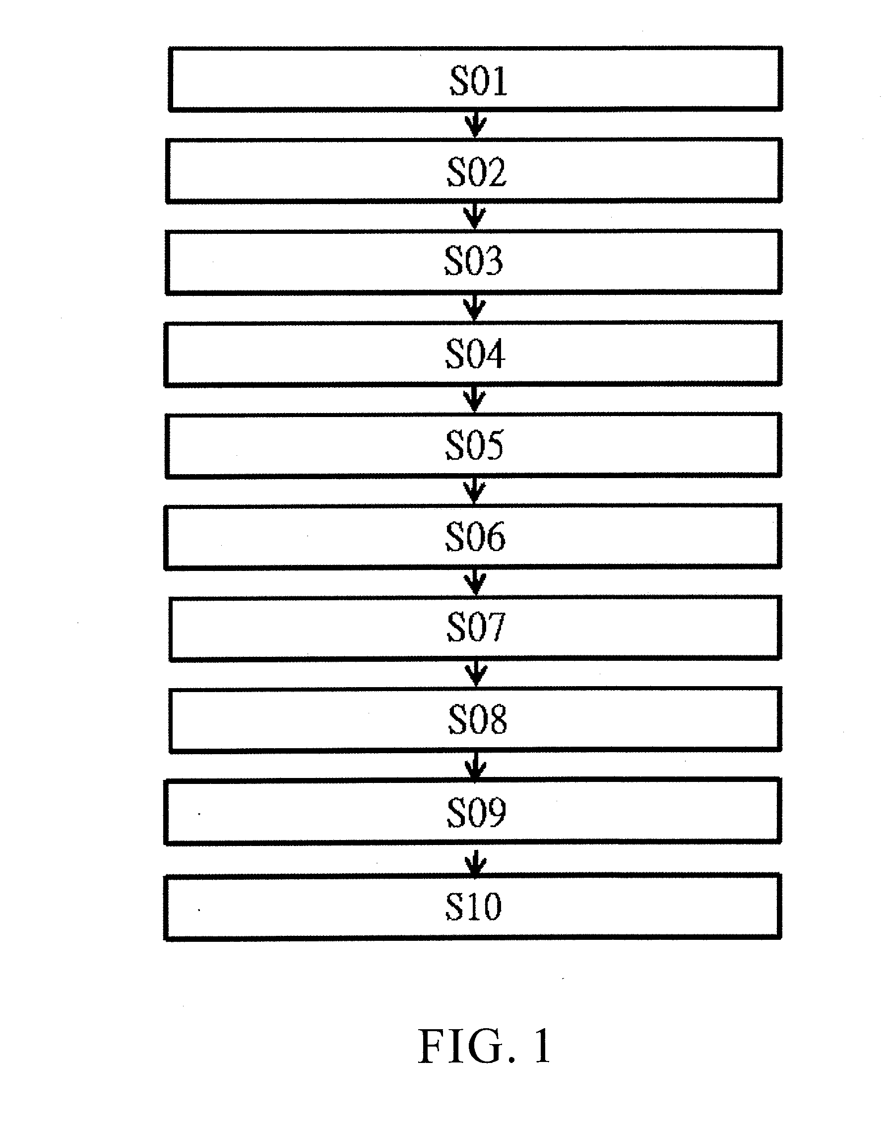
[0031]FIG. 1 is a flow chart of a method of detecting the states of a battery according to the present invention. As shown in the diagram, according to the present invention, the method of detecting the states of a battery is applicable to figuring out an overall battery health status index. The method comprises the steps below.

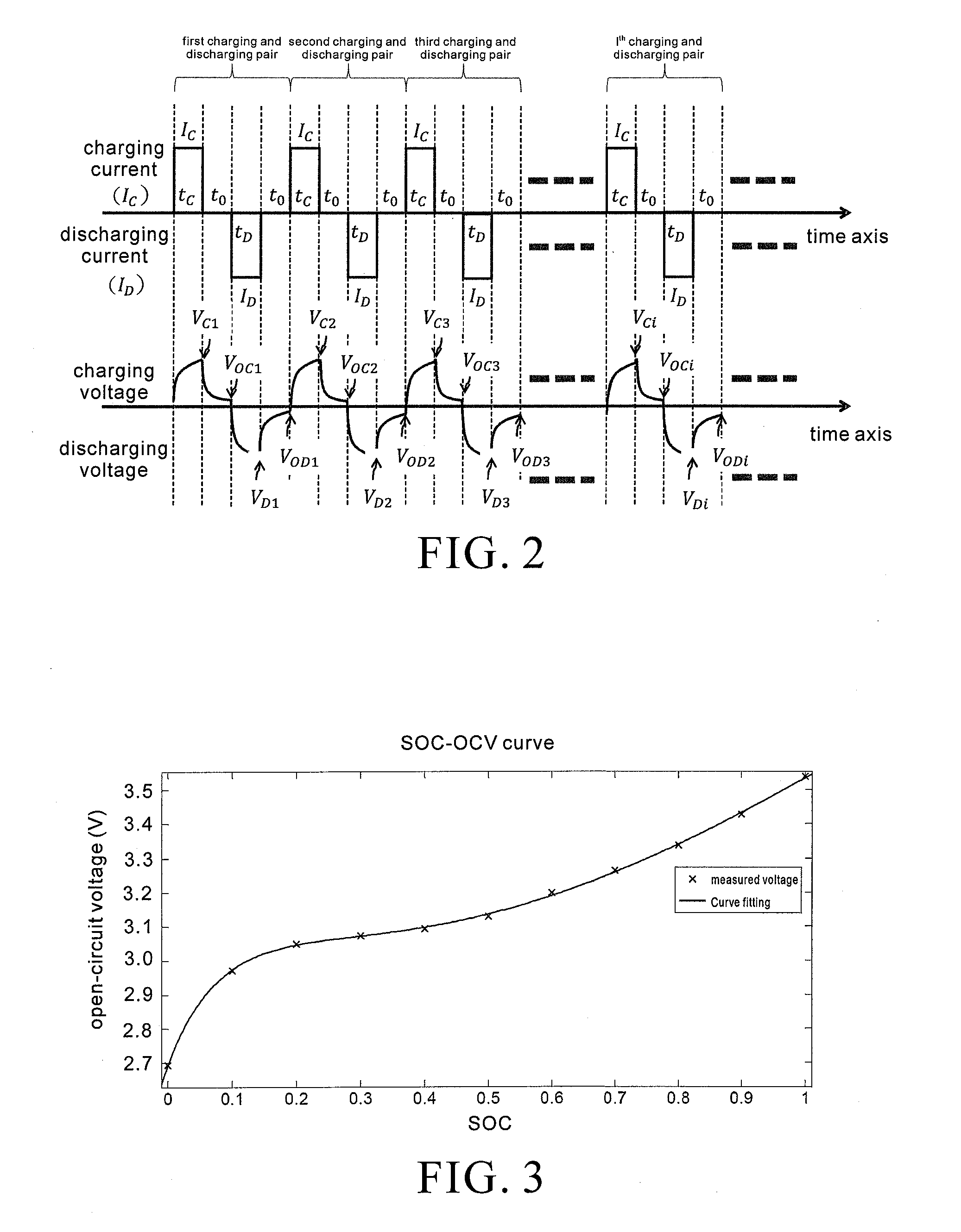
[0032]Step S01: setting control parameters of a charging / discharging pulse pair test, wherein the control parameters include charging pulse current (IC), discharging pulse current (ID), charging pulse time width (tC), discharging pulse time width (tD), open-circuit time width (t0), and the number N of charging and discharging pulse pairs, to provide the charging and discharging pulse waveform...


PUM


Abstract

A method and apparatus of detecting the states of a battery involve passing test-oriented charging and discharging pulse pair to a battery under test, and retrieving parameters of the battery, such as voltage, current, and temperature, which respond to the charging and discharging pulse pair, so as to estimate the battery states. The battery states include information pertaining to open-circuit voltage, internal resistance, capacitance, state of charge, and state of health of the battery. The battery state-related information is conducive to quick battery state detection and grading.

Description

FIELD OF TECHNOLOGY[0001]The present invention relates to battery state detection technology, and more particularly, to a method and apparatus of detecting the states of a battery, which apply to second-use applications of batteries retired from motor-driven carriers.BACKGROUND[0002]With fossil fuels dwindling and power battery technology developing, human beings attach increasingly great importance to issues, such as energy saving, carbon reduction, green energy sources, and environmental protection, with a view to protecting the environment of the Earth and coping with the climate changes of the Earth. Motor-driven carriers like electric motorcycles and electric buses are emerging under the auspices of governments around the world. It is predicted that the electric vehicle market will become sophisticated and widespread in years to come.[0003]A power battery is intended to power a motor-driven carrier, but it ages with cumulative working hours and mileage. Causes and signs of batt...

Claims


Application Information

Patent Timeline
23 Jun 2016
Publication
US20160178706A1
IPC
G01R31/36
CPC
G01R31/3679; G01R31/3675; G01R31/3651; G01R31/389; G01R31/3835; G01R31/392; G01R31/367
Inventors
LIU, CHIH-PENG; HSIAO, WEI-MIN