
Tube amplifier assembly having a power tube and a capacitor assembly

a technology of capacitor assembly and power tube, which is applied in the direction of transit tube vessel/container, amplifier with transit-time effect, fixed capacitor details, etc., can solve the problems of limiting the options available for controlling the electrical performance of the rf amplification system, the socket is expensive, and the problem of limiting the options

Active Publication Date: 2016-06-23
GENERAL ELECTRIC CO
View PDF0 Cites 14 Cited by
  • Summary
  • Abstract
  • Description
  • Claims
  • Application Information

AI Technical Summary

Benefits of technology

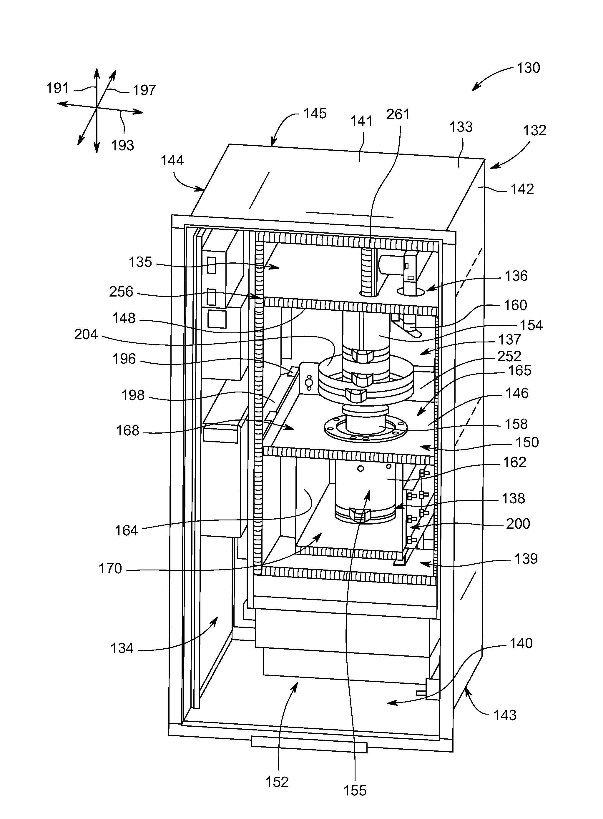
The invention is a tube amplifier assembly that includes a grounding deck and a power tube positioned within the deck's opening. The assembly also has a capacitive plate and an interposed plate that form a capacitor assembly that provides capacitance. The invention also includes flexible conductive elements that electrically connect the power tube to the capacitive plate. The technical effect of this invention is to provide an efficient and reliable tube amplifier assembly that improves the performance and reliability of the amplifier.

Problems solved by technology

The socket, however, can be expensive and can limit the options available for controlling the electrical performance of the RF amplification system.
It can be a challenge, however, to connect the power tube to the grounding deck without a socket and be capable of operating within the very high frequency (VHF) band or higher while achieving a designated efficiency.
Socket-mounted power tubes, however, may require that a separate device be installed for monitoring the signals.

Method used


Image

  • Tube amplifier assembly having a power tube and a capacitor assembly
  • Tube amplifier assembly having a power tube and a capacitor assembly
  • Tube amplifier assembly having a power tube and a capacitor assembly

Examples


Embodiment Construction

[0024]The following detailed description of certain embodiments will be better understood when read in conjunction with the appended drawings. To the extent that the figures illustrate diagrams of the functional blocks of various embodiments, the functional blocks are not necessarily indicative of the division between hardware circuitry. For example, one or more of the functional blocks (e.g., processors or memories) may be implemented in a single piece of hardware (e.g., a general purpose signal processor or a block of random access memory, hard disk, or the like) or multiple pieces of hardware. Similarly, the programs may be stand alone programs, may be incorporated as subroutines in an operating system, may be functions in an installed software package, and the like. It should be understood that the various embodiments are not limited to the arrangements and instrumentality shown in the drawings.

[0025]As used herein, an element or step recited in the singular and proceeded with t...


PUM


Abstract

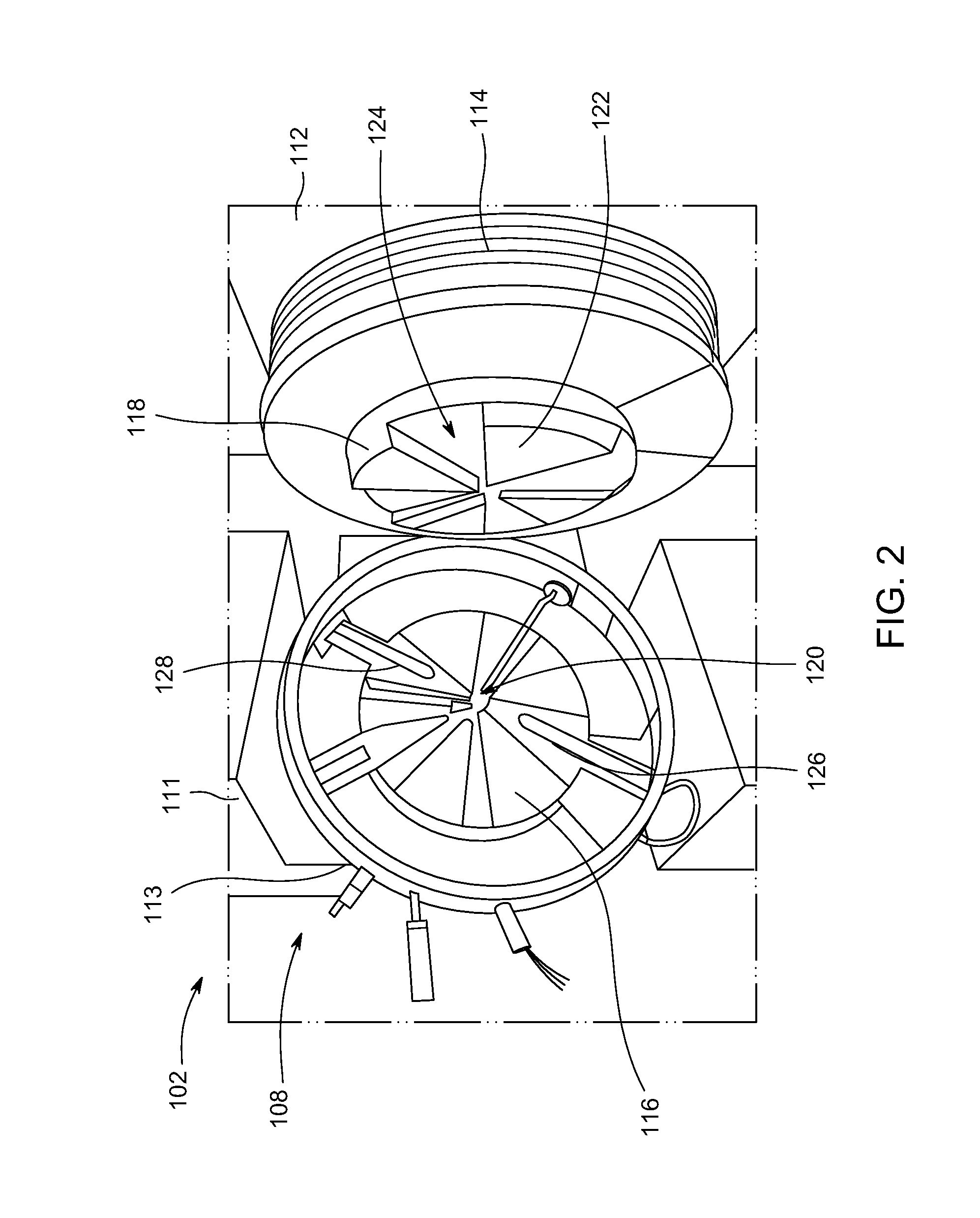
Tube amplifier assembly including a power tube that is configured to be coupled to a grounding deck and positioned within an opening of the grounding deck. The tube amplifier assembly also includes a tube adapter that is configured to be coupled to the grounding deck. The tube adapter has a capacitive plate that extends parallel to the grounding deck and an adapter wall that is coupled to the capacitive plate. The tube adapter has an adapter opening that is aligned with the deck opening to form a tube passage. The tube adapter includes flexible conductive elements that are electrically coupled to the capacitive plate and surround the tube passage. The flexible conductive elements engage the power tube in the tube passage and electrically couple the power tube to the capacitive plate. The grounding deck and the capacitive plate form a capacitor assembly.

Description

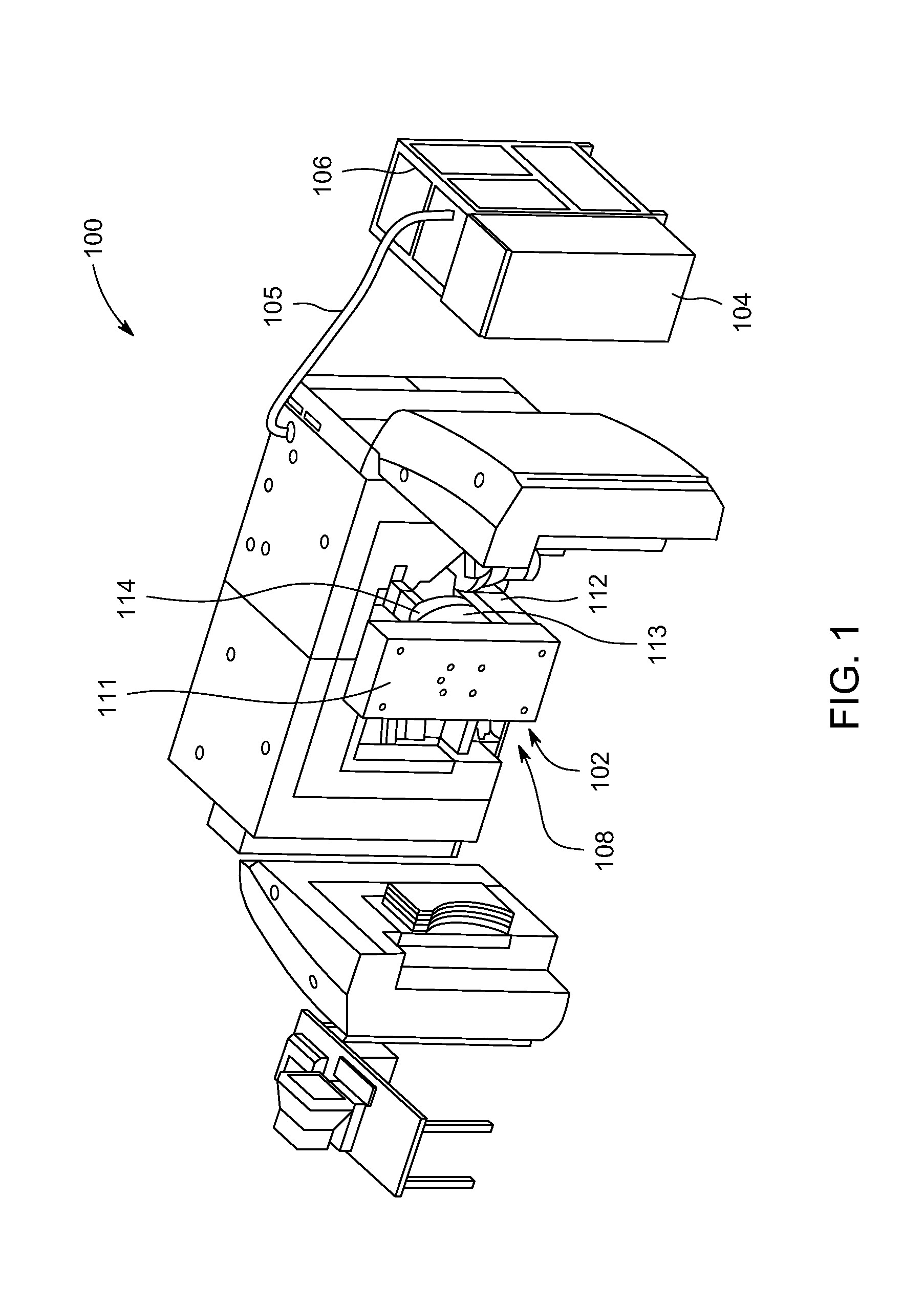
CROSS-REFERENCE TO RELATED APPLICATIONS[0001]The subject matter set forth herein is similar to subject matter described in U.S. application Ser. Nos. ______ (having Attorney Docket Nos. 278351 (553-1926); 278349 (553-1928US1); and 278350 (553-1929US1), respectively), which are filed on the same day as the present application. Each of the above applications is incorporated herein by reference in its entirety.BACKGROUND[0002]The subject matter herein relates generally to radio-frequency (RF) power generators and, more particularly, to RF power generators that utilize power electron vacuum tubes.[0003]Radioisotopes (also called radionuclides) have several applications in medical therapy, imaging, and research, as well as other applications that are not medically related. Systems that produce radioisotopes typically include a particle accelerator, such as a cyclotron, that accelerates a beam of charged particles (e.g., H−ions) and directs the beam into a target material to generate the ...

Claims


Application Information

Patent Timeline
IPC IPC(8): H03F3/22H01G4/40H01G4/002H03F3/189
CPCH03F3/22H03F3/189H03F2200/267H01G4/002H03F2200/451H01G4/40H05H2007/025H01J23/12H01G4/30
Inventor BAECKLUND, ANDREAS
Owner GENERAL ELECTRIC CO
Learn More