Illumination optical system for endoscope

an optical system and endoscope technology, applied in applications, lighting and heating apparatus, instruments, etc., can solve the problems of ineffective use of illumination light, small illumination light at the left and right ends of the screen, and inability to reduce etc., to achieve easy insertion of the insertion tube 101, prevent the effect of reducing the use efficacy of illumination light, and high brightness

Active Publication Date: 2016-07-07
HOYA CORP
View PDF3 Cites 86 Cited by
  • Summary
  • Abstract
  • Description
  • Claims
  • Application Information

AI Technical Summary

Benefits of technology

[0052]The cross section of each of the concave lens parts 8A and 8B according to the embodiment in the xz plane and the yz plane has a spherical shape, and the surface of each of the concave lens parts 8A and 8B is formed to be a toroidal surface of which central symmetric axis is substantially parallel with x-axis; however, the present invention is not limited to such a configuration. For example, the surface of each of the concave lens parts 8A and 8B may be configured to be a toroidal surface of which center symmetric axis is inclined with respect to x-axis in the xz plane. Alternatively, the surface of each of the concave lens parts 8A and 8B may be formed to be an anamorphic surface having different curvatures between x-axis direction and y-axis direction. In these examples, the same advantageous effects as those of the above described embodiment can be achieved.
[0053]Optical axes OC of the concave lens parts 8A and 8B of the cap 3 are shifted respectively from optical axes OL of the light-distribution windows 1A and 1B and the light guides 4A and 4B, and the concave lens parts 8A and 8B are disposed to be slightly shifted respectively toward the center of the tip end face 10. As a result, the light distribution windows 1A and 1B are disposed on the outside relative to the concave lens parts 8A and 8B, respectively, and therefore the illumination light which has passed through the concave lens parts 8A and 8B is emitted while being inclined toward the negative side of x-axis and the positive side of x axis, respectively, in comparison with the case where the concave lens parts 8A and 8B are not decentered. As a result, the scattering effect in x-axis direction by the concave lens parts 8A and 8B becomes larger in comparison with the case where the concave lens parts 8A and 8B are not decentered.
[0054]The illumination light which has been emitted from the light-distribution windows 1A and 1B and is scattered from the concave lens parts 8A and 8B is emitted from a lateral surface 12 or an upper surface 11 (the positive side in z-axis direction) of the cap 3 after propagating through the cap 3. The intensity distribution of the emitted illumination light becomes a laterally long distribution elongated in x-axis direction. In this embodiment, each of the concave lens parts 8A and 8B of the cap3 has a larger refractive power in x-axis direction, and the concave lens parts 8A and 8B are decentered from the light-distribution windows 1A and 1B, respectively. Therefore, the degree of scattering effect of the illumination light is larger in x-axis direction, and when a monitor having a laterally long displaying area is used, the intensity distribution of the illumination light can be made consistent with the aspect ratio of the monitor. As a result, it becomes possible to prevent decrease of the use efficacy of the illumination light due to the fact that an area not displayed on the monitor is illuminated, and thereby it becomes possible to obtain an image having a high brightness over the entire display area.
[0055]In FIG. 2B, the lateral surface 12 of the cap 3 is formed to be perpendicular to the tip end face 10 of the insertion tube 101; however, as shown in FIG. 2C the lateral surface 12 may be formed to have an inclined surface 9 so that the cap 3 becomes thinner toward the tip side (the positive side in z-axis direction). As a result, it becomes possible to easily insert the insertion tube 101 into a body cavity while decreasing resistance which the cap 3 receives from a body cavity

Problems solved by technology

Therefore, when a monitor having a laterally long aspect ratio is used, the amount of illumination light at the left and right ends on the screen becomes small or areas outside the screen in the longitudinal direction may be illuminated uselessly.
In this case, the illumination light cannot be used effectively.
Further, since the ring-shaped fiber is used, the diameter of the tip portion of the insertion tube is determined depending on the shape of the fiber, and therefore it is difficult to decrease the diameter of the tip portion.
However, there is a problem that, for the light guides disposed on the left and right sides with respect to the

Method used


Image

  • Illumination optical system for endoscope
  • Illumination optical system for endoscope
  • Illumination optical system for endoscope

Examples


Embodiment Construction

[0041]Hereinafter, an illumination optical system for an endoscope according to an embodiment of the invention is described with reference to the accompanying drawings.

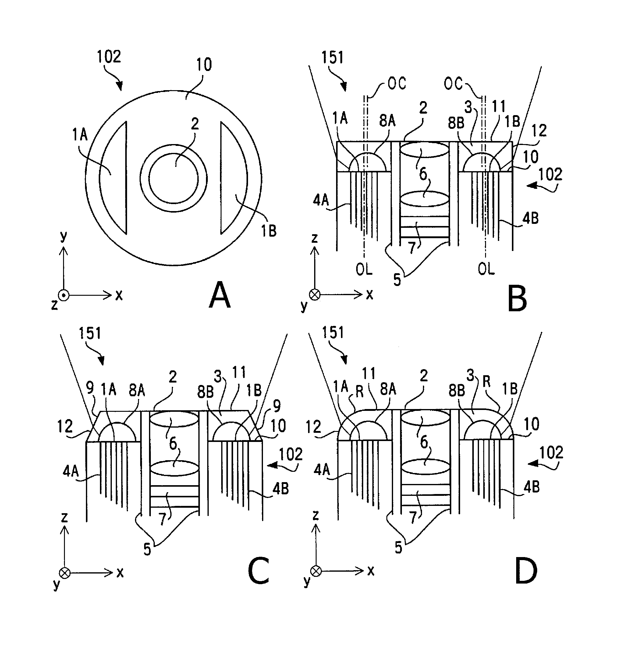
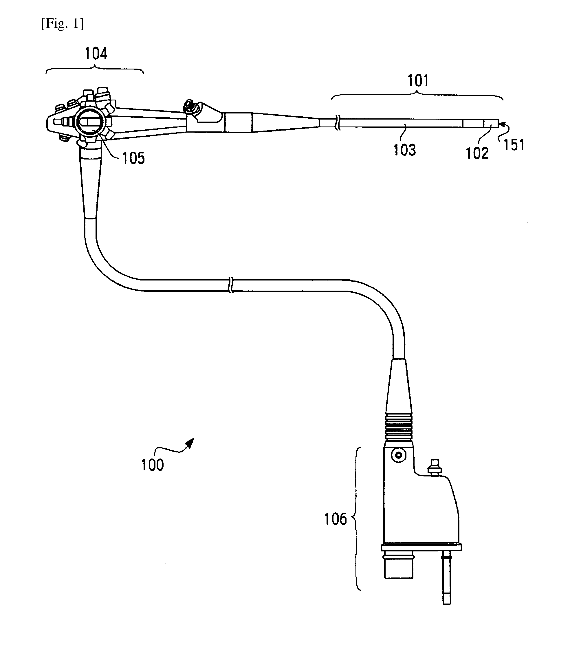
[0042]FIG. 1 illustrates an outer appearance of an endoscope 100 having an illumination optical system 151 according to the embodiment. The endoscope 100 includes a tube-like insertion tube 101 covered with an elastic sheath. At a tip of the insertion tube 101, a tip portion 102 covered with a resin housing having rigidity is provided. A bending part disposed on the front side of the tip portion 102 of the insertion tube 101 is formed to be freely bent through remote operation (specifically, a rotation operation to a bending operation knob 105) from an operation unit 104 coupled to the proximal end of the insertion tube 102. This bending mechanism is a known mechanism installed in a general endoscope, and is configured such that a bending part 103 is bent by drawing of operation wires in conjunction with the rotation ...


PUM


Abstract

An illumination optical system for an endoscope includes two light guides disposed in an insertion tube in a first direction to sandwich a center of the insertion tube therebetween; an observation window on a tip end face of the insertion tube; two concave lens parts having negative powers sandwiching the observation window at positions facing end faces of two light guides on the tip end face of the insertion tube. The end face of each of the two light guides has a smaller width in the first direction than a width in a second direction perpendicular to the first direction; each of the two concave lens parts has a larger negative power in the first direction than a negative power thereof in the second direction; and of illumination light which has propagated through each of the two concave lens parts after being emitted from each of the two light guides.

Description

TECHNICAL FIELD[0001]The present invention relates to an illumination optical system used for an endoscope.BACKGROUND ART[0002]An endoscope configured such that a light-distribution window through which illumination light for illuminating an observation target area is emitted and an observation window through which the illumination light reflected from the observation target area is received are provided at a tip portion of an insertion tube of the endoscope is known. The insertion tube of the endoscope of this type is formed in a shape of an elastic tube, and a light guide for introducing the illumination light to the tip portion is provided in the inside of the insertion tube. In the observation window, an objective lens is provided, and object light reflected from the observation target area is received by an image pickup device, such as a CCD (Charge Coupled Device), via the objective lens. The object light received by the image pickup device is subjected to signal processing an...

Claims


Application Information

Patent Timeline
IPC IPC(8): G02B23/24A61B1/00A61B1/06F21V8/00
CPCG02B23/2469G02B6/0008A61B1/0661A61B1/00163A61B1/00137G02B23/24G02B23/26A61B1/00096A61B1/05A61B1/07G02B6/005
Inventor FUJII, HIROAKI
Owner HOYA CORP
Why Eureka
Try Eureka