Multimodal imaging apparatus

a multi-modal imaging and apparatus technology, applied in tomography, instruments, applications, etc., can solve the problems of difficult upgradability, less possible savings, and complicated supply chain of different imaging systems, so as to reduce the amount of electronics, save costs, and achieve high light output

Inactive Publication Date: 2016-07-21
KONINKLJIJKE PHILIPS NV
View PDF2 Cites 17 Cited by
  • Summary
  • Abstract
  • Description
  • Claims
  • Application Information

AI Technical Summary

Benefits of technology

[0018]In another embodiment the multimodal imaging apparatus further comprises a common gantry for supporting the scintillator and the photodetector in the first operation mode and in the second operation mode. In contrast to previous solutions or systems, which usually make use of two separate gantries and two separate readout electronics for generating images of a process in a subject causing the emission of low energy gamma quanta (as in SPECT imaging) on the one hand and the emission of high energy gamma quanta (as in PET imaging) on the other, the present invention allows saving costs by using a single, i.e. common, gantry. It is further possible to reduce the amount of electronics, e.g. by using one processor (readout electronics) for processing the signals for both low energy and high energy signals instead of two separate processors according to further embodiments of the present invention. By making use of a common gantry the present invention allows imaging the same area of interest (in a subject) without requiring moving the subject versus the gantry. This allows efficiently using two different imaging modalities for providing images of a single area of interest in a subject and has the advantage that the subject does not need to be moved. Moving the subject could have an influence on the process or the organ being imaged and may make it difficult to obtain PET and SPECT images from the very same (spatiotemporal) area of interest.
[0019]According to another embodiment of the present invention the multimodal imaging apparatus further comprises a collimator for filtering the incident gamma quanta based on the angle of incident in the first operation mode. Such a collimator usually refers to a device for narrowing a beam of gamma quanta (or other particles) and may, e.g. comprise a block of a non-transparent shielding material such as lead, molybdenum, tungsten or depleted uranium including a plurality of appropriately aligned boreholes. Also an arrangement of folded sheets of such non-transparent materials may be comprised in the collimator. Narrowing herein means to align the directions of motions of the different gamma quanta. The main effect of the collimator is the selection of quanta that are emitted from the radioisotope under certain angles. Thereby imaging by use of parallel holes or a pinhole is enabled, similar to the use of a lens or a pinhole in optical imaging. Another advantage of making use of collimator in the present invention is that it allows filtering out gamma quanta, in particular gamma rays, that are not travelling in the desired direction, i.e. that do not originate from the area of interest. The angle of incidence under which incident gamma quanta can pass the collimator is thereby in particular specified as the direction of the subject to be examined. The resulting image is only based on the desired gamma quanta, i.e. the gamma quanta that are not filtered out. The collimator may thereby also be adjustable, i.e. variable in its filtering angle. SPECT imaging, e.g., usually requires the use of a collimator as single photons are detected and the imaging is based on all captured gamma quanta. Thus, if gamma quanta originating from other sources than the process in the subject to be imaged were also captured, the generated image would not be meaningful with respect to the process in the subject representing the originally desired purpose of the imaging but would show a range of side effect obscuring the intended image. In PET imaging, in contrast thereto, usually no collimator is required because the incident gamma quanta are filtered based on a coincidence detection in which only incident gamma quanta are considered in the imaging that have a coincident event on the opposite side of the subject.
[0020]In another embodiment the scintillator elements include high energy scintillator elements for capturing high energy gamma quanta and low energy scintillator elements for capturing low energy gamma quanta and/or the photodetector is configured for operation in photon counting mode, wherein the dynamic range of the photodetector is configured to capture scintillation photons emitted by both the high energy scintillator elements and by the low energy scintillator elements. Usually scintillators and in particular scintillator arrays comprise one single type of scintillator elements only. Depending on the material and the dimensions of these scintillator elements their reaction in response to incident gamma quanta varies significantly. If, e.g. the scintillator elements comprise organic crystals or liquids the reaction, i.e. the amount emitted scintillation photons in response to incident gamma quanta, may be particularly suited for the detection of heavy ions. According to the present invention, preferably inorganic scintillators such as high-Z inorganic crystals like LYSO or BGO, YAG:Ce, ceramic garnets based on the formula (M1,M2)3(M3,M4)5O12:Ce with M1 and M2 elements of the group (Sc, Y, rare earth metals, Mg, Ca) and M3 and M4 of the group (Al, Ga, In, Sc, L

Problems solved by technology

This leads to a more complicated supply chain for the different imaging systems and difficulties in the upgradability.
Usually, PET and SPECT systems require different mechanical structures, different data acquisition paths and different photodetectors or combinations of photodetectors leading to little possible savings when combining the two imaging modalities in order to obtain a multimodal imaging device for providing images based on both imaging modalities.
One disadvantage of this solution, how

Method used


Image

  • Multimodal imaging apparatus
  • Multimodal imaging apparatus
  • Multimodal imaging apparatus

Examples


Embodiment Construction

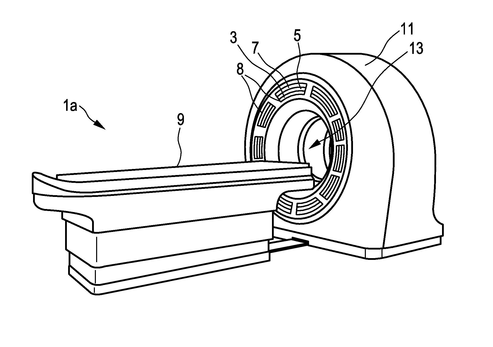
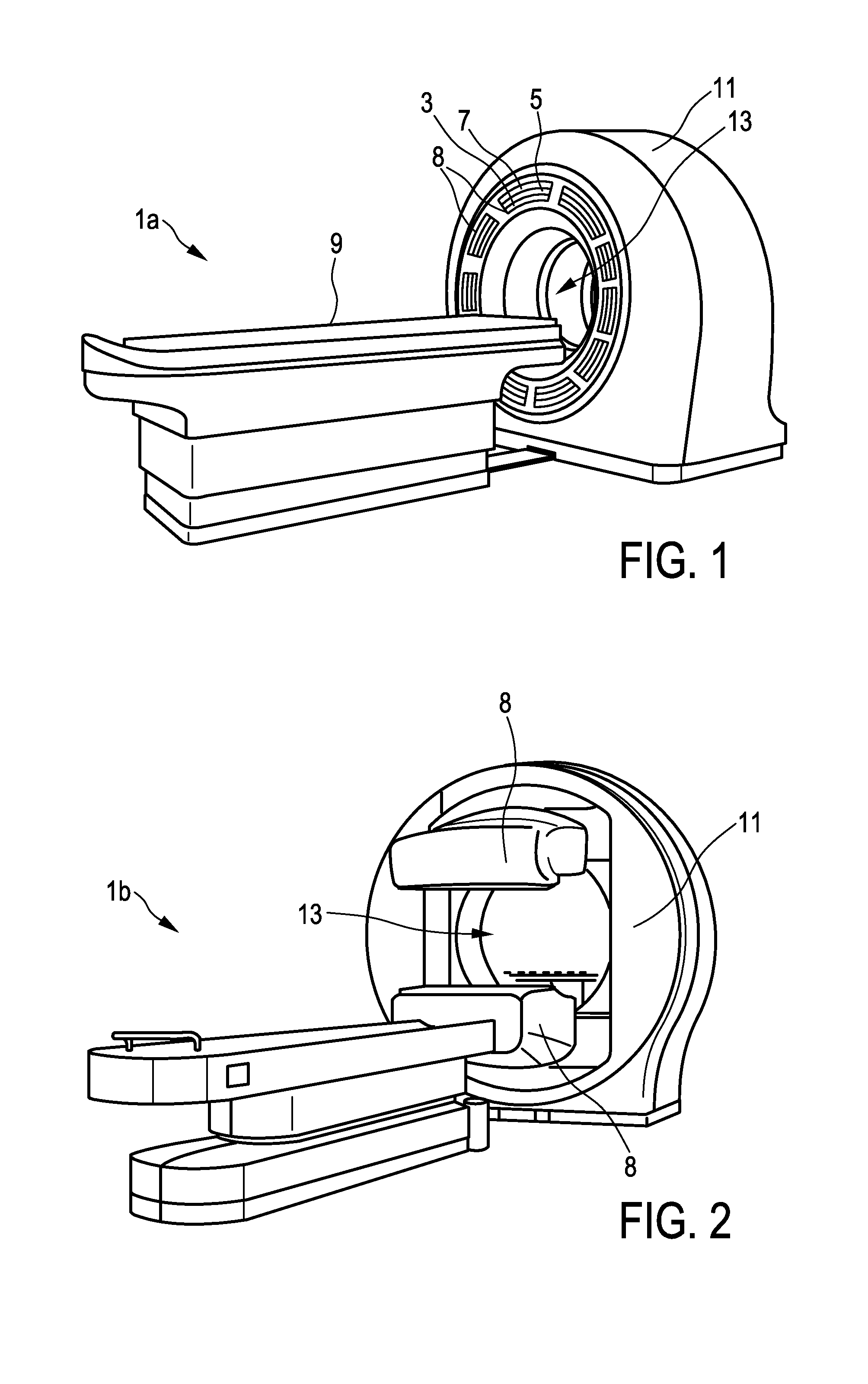
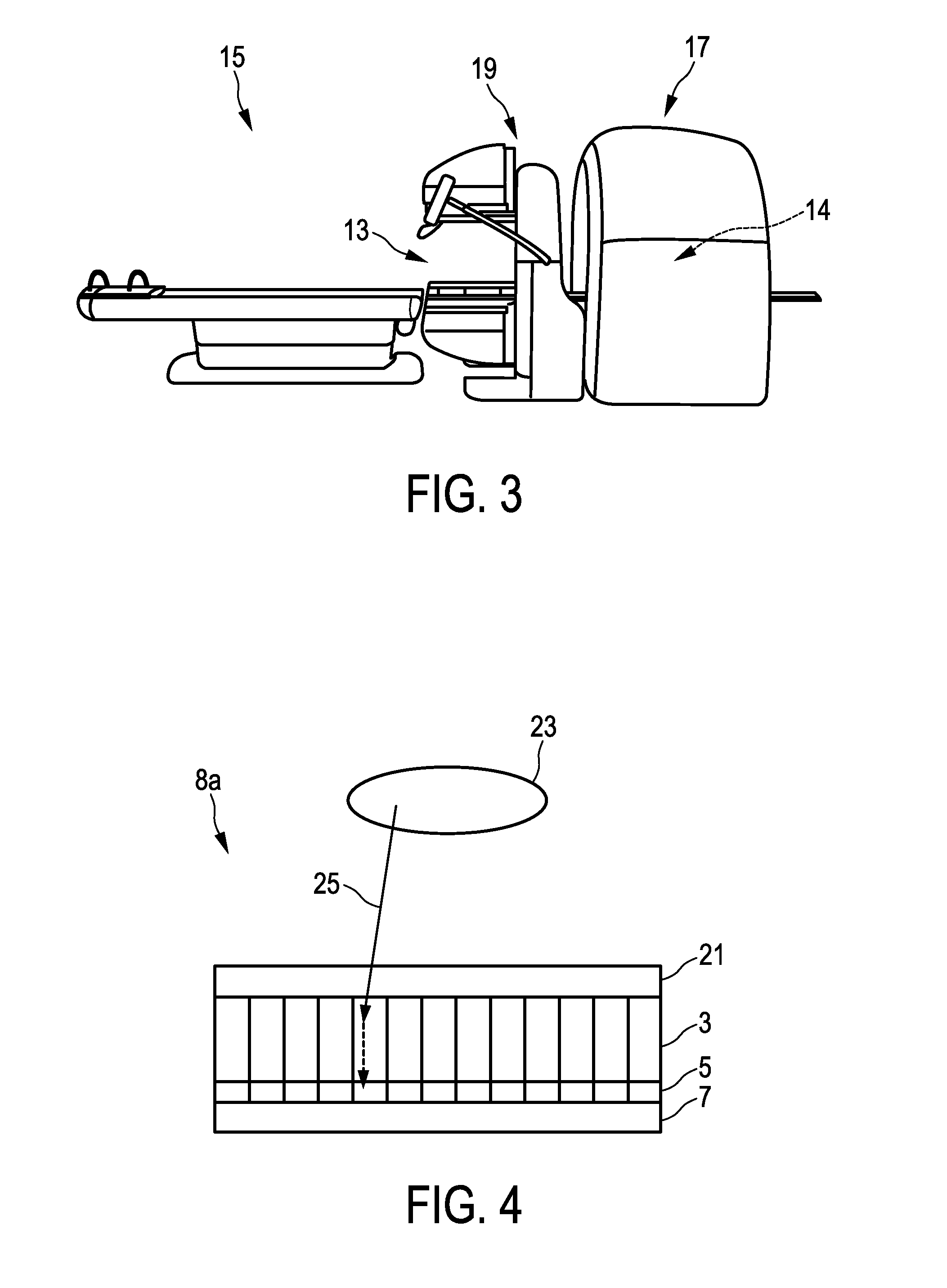
[0051]In FIG. 1 there is illustrated a first embodiment of a multimodal imaging apparatus 1a according to the present invention. The apparatus 1a comprises a scintillator 3 for capturing incident gamma quanta generated by a radiotracer and for emitting scintillation photons in response to captured gamma quanta and a photodetector 5 for capturing the emitted scintillation photons and for determining a spatial distribution of the scintillation photons (e.g. a charge distribution). The apparatus further comprises a readout electronics 7 for determining the impact position of an incident gamma quantum in the scintillator 3 based on the spatial distribution of the scintillation photons. A combination of scintillator 3, photodetector 5, and at least part of the readout electronics 7 may also be referred to as detection module 8. As illustrated in FIG. 1 the multimodal imaging apparatus 1a comprises multiple detection modules 8 attached to a common gantry 11. The number of detection module...


PUM


Abstract

The present invention relates to a multimodal imaging apparatus (1a, 1b) for imaging a process (63) in a subject (23), said process (63) causing the emission of gamma quanta (25, 61), said apparatus (1a, 1b) comprising a scintillator (3) including scintillator elements (31) for capturing incident gamma quanta (25, 61) generated by the radiotracer and for emitting scintillation photons (26) in response to said captured gamma quanta (25, 61), a photodetector (5) including photosensitive elements (33) for capturing the emitted scintillation photons (26) and for determining a spatial distribution of the scintillation photons, and a readout electronics (7) for determining the impact position of an incident gamma quantum in the scintillator (3) and/or a parameter indicative of the emission point of the gamma quantum (25, 61) in the subject (23) based on the spatial distribution of the scintillation photons, wherein the imaging apparatus (1a, 1b) is configured to be switched between a first operation mode for detecting low energy gamma quanta and a second operation mode for detecting high energy gamma quanta, wherein the high energy gamma quanta have a higher energy than the low energy gamma quanta, and the scintillator (3) is arranged to capture incident gamma quanta (25, 61) from the same area of interest (65) in the first operation mode and in the second operation mode without requiring a relative movement of the subject (23) versus the scintillator (3), wherein the scintillator (3) comprises an array of scintillator elements (31) including a first region with high energy scintillator elements (27) for capturing high energy gamma quanta and a second region with low energy scintillator elements (29) for capturing low energy gamma quanta; and/or the apparatus (1a, 1b) further comprises a positioning mechanism (35) for changing the orientation and/or position of the scintillator elements (31), in particular for tilting the scintillator elements (31), to switch the imaging apparatus (1a, 1b) between the first operation mode and the second operation mode.

Description

FIELD OF THE INVENTION[0001]The present invention relates to a multimodal imaging apparatus for imaging a radiotracer distribution within a subject.BACKGROUND OF THE INVENTION[0002]Single Photon Emission Computed Tomography (SPECT) and Positron Emission Tomography (PET) are, either self-contained or in combination with Computed Tomography (CT) or Magnetic Resonance Imaging (MRI), two common techniques for imaging the human body or parts thereof. In particular, PET and SPECT allow imaging organs or metabolic processes in the human body and, e.g., determine therefrom the progress of a disease. For this, a patient is usually administered a radioactive tracer substance emitting particles, i.e. radiation, that can be captured and used as a basis for imaging. Further applications include preclinical studies, wherein small animals are imaged in order to determine the effects of new medication or treatment approaches. Also other imaging applications outside the field of medicine exist relyi...

Claims


Application Information

Patent Timeline
IPC IPC(8): G01T1/16A61B6/00A61B6/03
CPCG01T1/1603A61B6/4417A61B6/037G01T1/2985
Inventor DA SILVA RODRIGUES, PEDRO JORGETRINDADE RODRIGUES, ANDREIA MARIA ARAUJOWIECZOREK, HERFRIED KARLVOGTMEIER, GEREON
Owner KONINKLJIJKE PHILIPS NV
Why Eureka
Try Eureka