Uniform Heat Distribution in Resistive Heaters For Anti-Icing and De-Icing

a resistive heater and heat distribution technology, applied in the direction of ohmic resistance heating, heating element shapes, electrical devices, etc., can solve the problems of changing the aerodynamic performance of the aircraft, posing potential problems to aircraft, and altering flight capabilities

Active Publication Date: 2016-08-04
BATTELLE MEMORIAL INST
View PDF10 Cites 64 Cited by
  • Summary
  • Abstract
  • Description
  • Claims
  • Application Information

AI Technical Summary

Benefits of technology

[0011]In a first aspect, the invention provides a lightweight and compact carbon-based heating device disposed on a substrate, comprising: two electrodes, each of which is bonded to the substrate by an adhesive; wherein the edge of the electrode closest to the substrate is defined as the bottom of the electrode and the edge furthest from the substrate is defined as the top of the electrode and wherein the edges of the electrode between the top and bottom are defined as the sides of the electrode; a conductive polymer bonded to at least one side of each electrode, wherein the conductive polymer is thickest near the bottom of each electrode and thinnest near the top of each electrode so as to form a sloped surface of the conductive polymer on the sides of each electrode; and a conductive CNT heater layer disposed between the sloped sides of the conductive polymer.

Problems solved by technology

Flight in icing conditions poses potential problems to aircraft.
Ice accumulation on critical surfaces can change the aerodynamic performance of the aircraft, altering flight capabilities.
Ice can also accumulate and then detach, where it may be ingested by the engine or cause other damage to the aircraft.
However, they require integration with the structural composite and cannot be retrofitted to existing aircraft.
Furthermore, the location of the heaters far below the surface, into a thermally conductive medium, means that they require substantial power to anti-ice / de-ice in light conditions below 0° F. or moderate icing conditions.
However it does not address the interface between the heating element and the electrodes.
The presence of hot spots in the heater, for example created by contact resistance at the electrode-heater interface, will cause these regions to overheat during powering.
At higher power densities, such as needed for icing conditions at temperature below 0° F. and airspeeds of about 150 to 180 knots or high liquid water content, these hot regions can cause degradation of the material, leading to failure of the system, or potential loss of structural integrity of the aircraft.
The maximum operating temperature of some carbon fiber aircraft is below 145° F. Any areas that are colder than the desired temperature serve as initiation points where ice will accrete and can be difficult or impossible to remove at a later time.
Furthermore, non-uniformities in the geometry, such as sharp ridges or defects on the surface, can serve as initiation points.
However, a challenge with this approach is the presence of gaps between heaters (for example, the gap between heaters 114 and 116 in FIG. 1).
In addition, the position where one heater joins the next is a geometric defect in the surface.
The surface can be smoothed by adding filler over the heaters and sanding; however, the presence of insulating filler over the surface reduces the heat output.
Furthermore, non-uniform application of filler also leads to formation of thermal non-uniformities in the system.

Method used


Image

  • Uniform Heat Distribution in Resistive Heaters For Anti-Icing and De-Icing
  • Uniform Heat Distribution in Resistive Heaters For Anti-Icing and De-Icing
  • Uniform Heat Distribution in Resistive Heaters For Anti-Icing and De-Icing

Examples


examples 1 to 8

Heating Performance of Film Heaters on Steel

[0074]Steel panels that were 5 inch long and 3 inch wide were primed with Deft 44-GN-072, MIL-PRF-85582D low density epoxy primer, to 9-10 mil wet thickness and cured according to manufacturer's instructions. These panels were used as substrates for heater fabrication. Alternatively, plastic substrates that were 5 mil thick, 3.75 inch long and 2.75 inch wider were glued to the primed steel. All substrates were scuffed, solvent wiped, and Corona treated prior to lead attachment. One of two types of leads was attached to the substrate—either Cu foil (0.005 inch thick and 0.2 in wide) or Cu braid that had been pressed to 0.005 in thick and 0.2 in wide.

[0075]The leads were adhered to the substrate as follows. In all cases, two roughly 2.5 inch to 3 inch long leads were placed in parallel, spaced 2 inch apart. They were attached with adhesive, as described below. Results are shown in Table 1.

[0076]The adhesive was mixed and cured according to t...

examples 13 to 16

Heating Performance of Heaters on Carbon Fiber Airfoil

[0082]Heaters were prepared according to previous examples 1, 3, and 5 with the exception that the base substrate was a primed carbon fiber composite airfoil shape. The samples were placed in a benchtop wind tunnel capable of operating at windspeed of 91 mph that was in a controlled temperature and humidity chamber. As shown by comparing 13 and 15 with 14 and 20 (Table 3), the use of a hybrid interface decreased the contact resistance and improved the thermal uniformity. The power density that could be operated before overheating and failing was 22 W / in2 at 0 to 10° F. and 91 mph, as opposed to 16 W / in2 and 12 W / in2 for the comparative example.

TABLE 3Description of Film Heaters on Primed CarbonFiber Airfoil, Tested in Benchtop Wind TunnelPowerContactDensity atResis-FailureExampleSubstrateLead Descriptiontance(W / in2)13Ultem attachedCu foil attached100% 16 at 0° F.to primedwith Devcon Epoxyand 91 mphcarbon fiberPlus having wideairf...

examples 17 to 20

Durability of Heaters on Carbon Fiber

[0083]Example 17. In this example a hybrid Cu—Ag-CNT interface is created that has a smooth transition

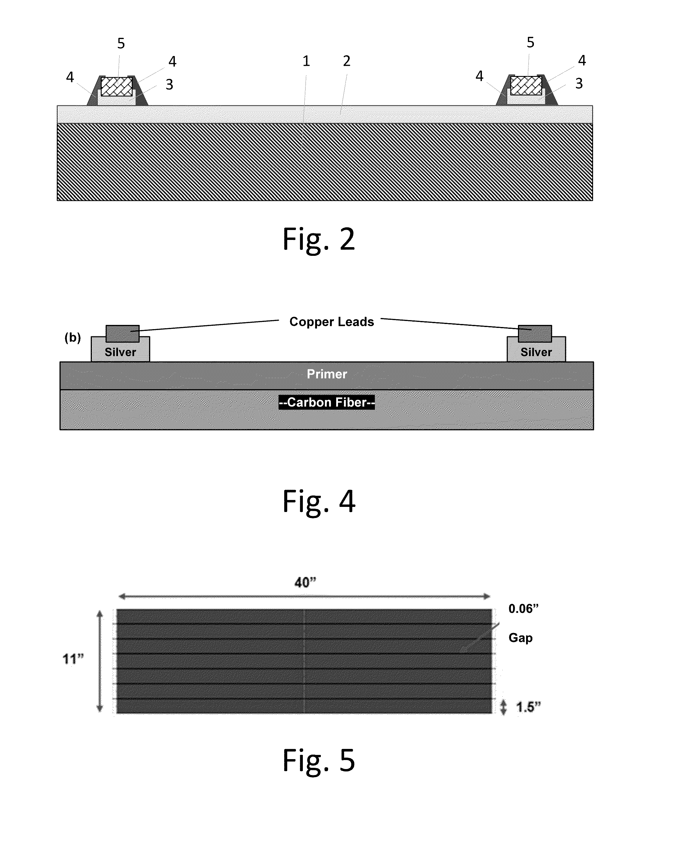
[0084]The configuration shown in FIG. 2 was prepared. A 4 inch by 4 inch square carbon fiber panel was primed with Deft 44-GN-072, MIL-PRF-85582D low density epoxy primer, to 9-10 mil wet thickness. The primer was cured at room temperature for at least 24 h. The surface was scuffed with green scotchbrite pad. Cu braid (HexWik W55) was pressed between two aluminum plates to create the electrodes having a thickness of 0.005±0.001 inches thick and 0.05 inches wide. The braid was either used as received, scuffed with 240 grit sandpaper, or etched with ammonium hydroxide and cleaned in ultrasonic bath. Loctite EA9395 was prepared according to the manufacturer's instructions. Two narrow lines, 2 inch long, were placed in parallel 2 inch apart in the center of the coupon, using a mask to meter the quantity; the mask was removed. The selected leads were ...


PUM


Abstract

The concept of the present invention describes configurations to provide uniform heat distribution of resistive heaters. This configuration allows successful anti-icing and deicing with relatively low applied power. One aspect involves the use of a thin film heater applied just underneath the topcoat to efficiently direct all heat to the surface, allowing anti-icing and de-icing with minimal power. This can be accomplished by employing a hybrid electrode interface, using a metal foil or metal braid that is attached to the aircraft surface with a structural adhesive that has been smoothed along the edges with metal-filled adhesive. Another aspect of the present invention uses an array of heater cells created as a single sheet and a heat spreading material, provided underneath or overtop of the heater cells.

Description

RELATED APPLICATIONS[0001]This application claims priority to U.S. Provisional Patent Application Ser. No. 62 / 100,440 filed 6 Jan. 2015.INTRODUCTION[0002]Flight in icing conditions poses potential problems to aircraft. Ice accumulation on critical surfaces can change the aerodynamic performance of the aircraft, altering flight capabilities. Ice can also accumulate and then detach, where it may be ingested by the engine or cause other damage to the aircraft. Icing conditions may be defined by the rate of accumulation of ice, dependent on environmental conditions such as temperature and liquid water content, flight conditions such as speed and altitude, and airfoil shape. Ice protection systems are used to enable flight in light to moderate icing conditions. A representative accretion rate for reference purposes is 0.25 to 1 inch per hour and 1 to 3 inches per hour for light and moderate icing, respectively. Generally, light conditions have a liquid water content of 0.125 to 0.25 g / m3...

Claims


Application Information

Patent Timeline
Patent Type & Authority Applications(United States)
IPC IPC(8): B64D15/12H05B3/48H05B3/00
CPCB64D15/12H05B3/48H05B3/0014H05B3/34H05B2203/011H05B2214/04H05B3/146H05B2203/013H05B2214/02H05B2214/03H02K3/50H02K3/522H02K5/225H02K2203/09
Inventor BURTON, BRETTHEINTZ, AMY M.BOSWORTH, KURTDUONG, TONYJANSEN, MIKE
Owner BATTELLE MEMORIAL INST
Why Eureka
Try Eureka