Apparatus for degassing a nuclear reactor coolant system

a technology for coolant systems and nuclear reactors, applied in nuclear elements, separation processes, greenhouse gas reduction, etc., can solve the problems of significant energy and significant building space and support systems, and achieve the effect of minimizing the required number of contactors and improving the efficiency of membranes

Inactive Publication Date: 2016-08-04
WESTINGHOUSE ELECTRIC CORP
View PDF2 Cites 6 Cited by
  • Summary
  • Abstract
  • Description
  • Claims
  • Application Information

AI Technical Summary

Benefits of technology

[0012]In one embodiment, a “sweep” gas system is connected to the outlet chamber for supplying a relatively small inert gas purge flow in the outlet chamber and preferably, the inert gas is nitrogen. The sweep gas, in combination with the application of a vacuum, enhances the efficiency of the membranes for dissolved gas removal, thus minimizing the required number of contactors. In still another embodiment, the contactor housing comprises a plurality of contactor housings connected in parallel. Alternately, the contactor housings may be connected in series. In still another embodiment, the contactor housing comprises a plurality of contactor housings with at least some of the plurality of contactor housings connected in parallel and some of the parallel connected contactor housings are connected in series with at least one other of the plurality of contactor housings. In still another embodiment, the contactors may be operated without a sweep gas, but may require additional contactors in series and / or parallel.

Problems solved by technology

This traditional approach requires significant energy to operate large vacuum pumps, multiple components, e.g., degasifier columns, transfer pumps, separator vessels, interconnecting piping, valves, and instrumentation, and requires significant building space and support systems, e.g., cooling / chilled water.

Method used


Image

  • Apparatus for degassing a nuclear reactor coolant system
  • Apparatus for degassing a nuclear reactor coolant system
  • Apparatus for degassing a nuclear reactor coolant system

Examples


Embodiment Construction

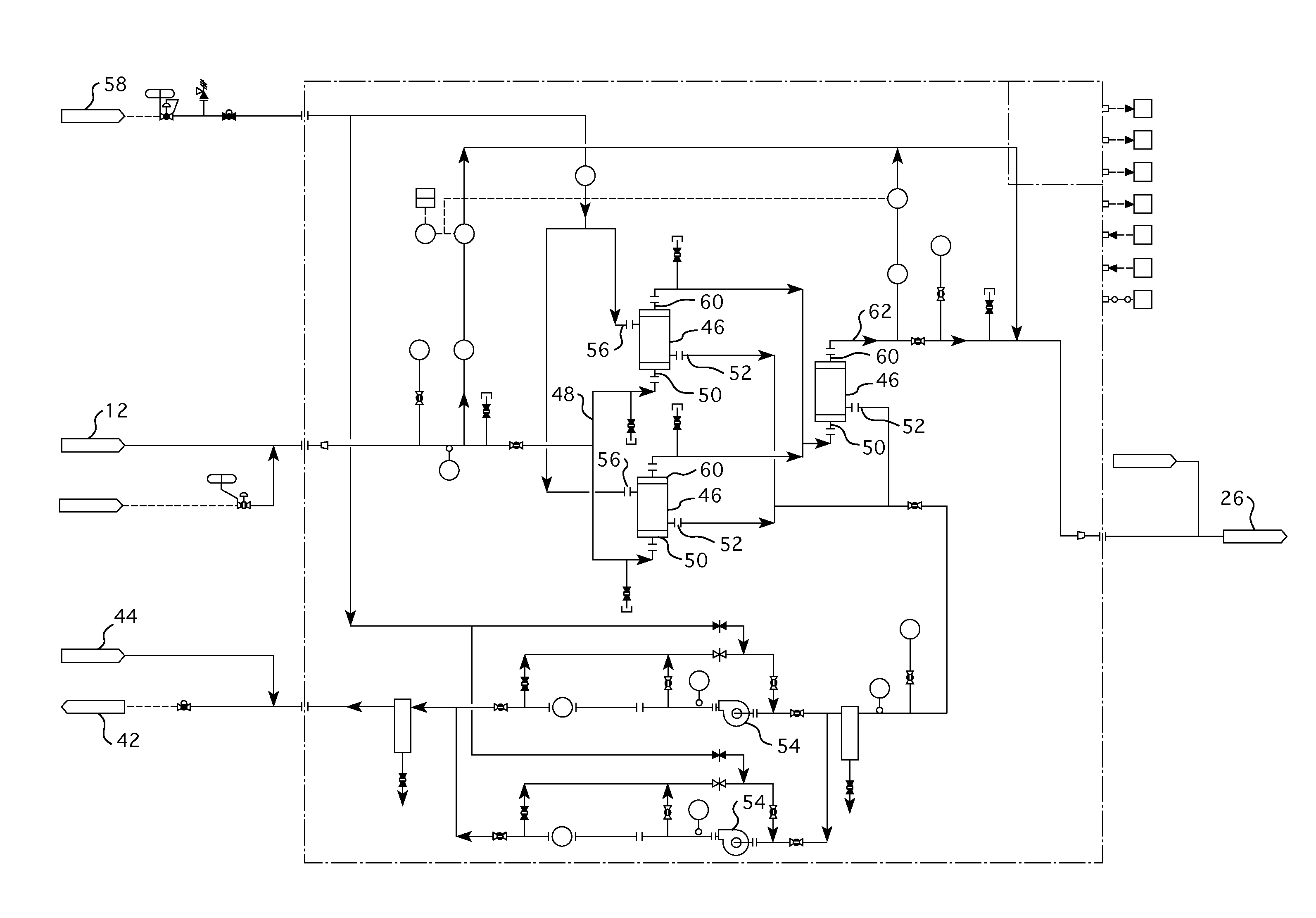
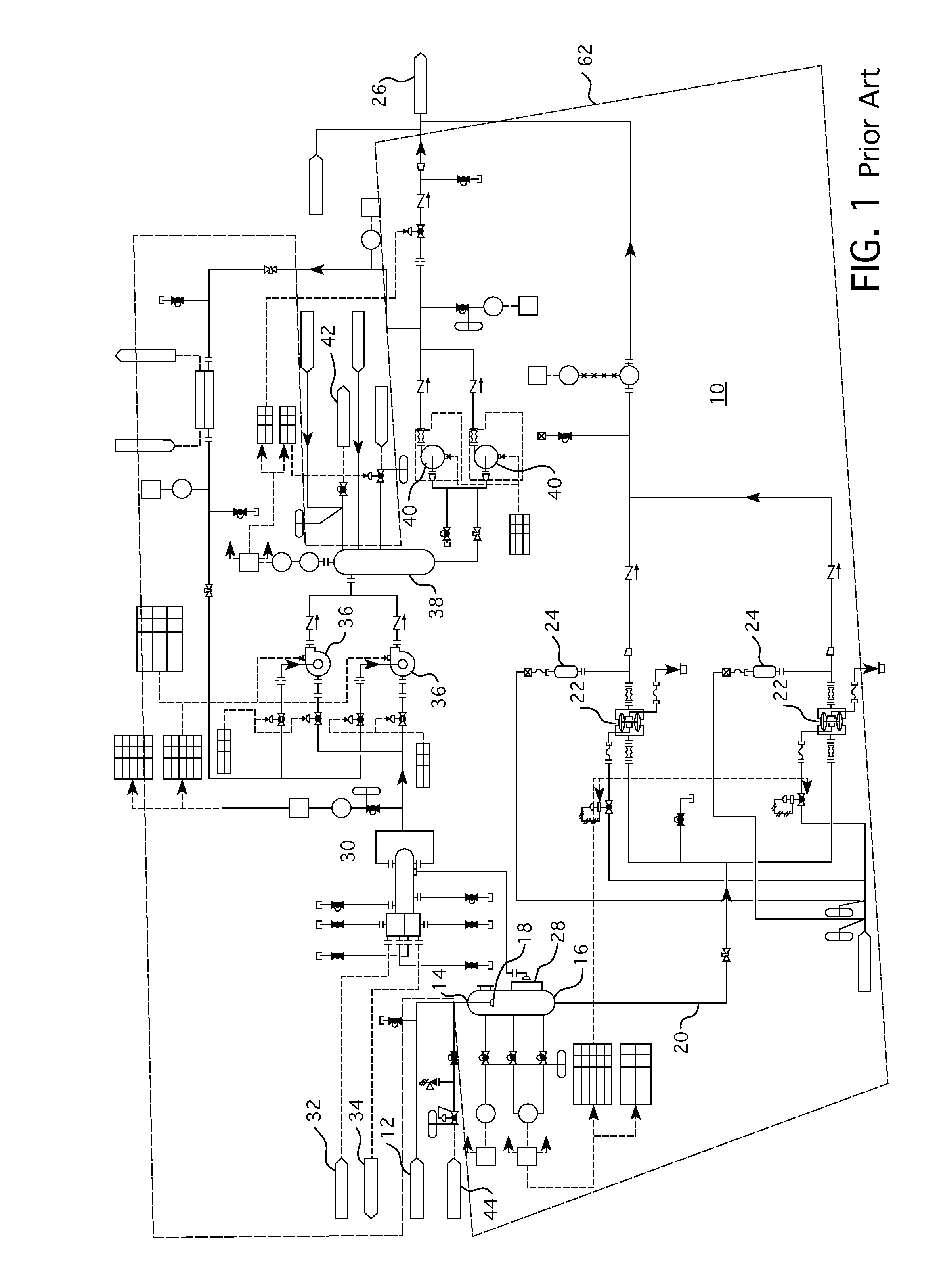
[0017]This invention utilizes a known and established technology of gas membranes to remove dissolved gases from the reactor coolant. While this is a known and proven technology for some applications, it has not been previously employed to handle mildly acidic and radioactive solutions as exists in interfacing with the primary coolant of a nuclear reactor system, as evidenced by the alternative reactor degasing systems proposed in the past and described in the evaluation of prior art set forth in the Background of U.S. Pat. No. 4,647,425.

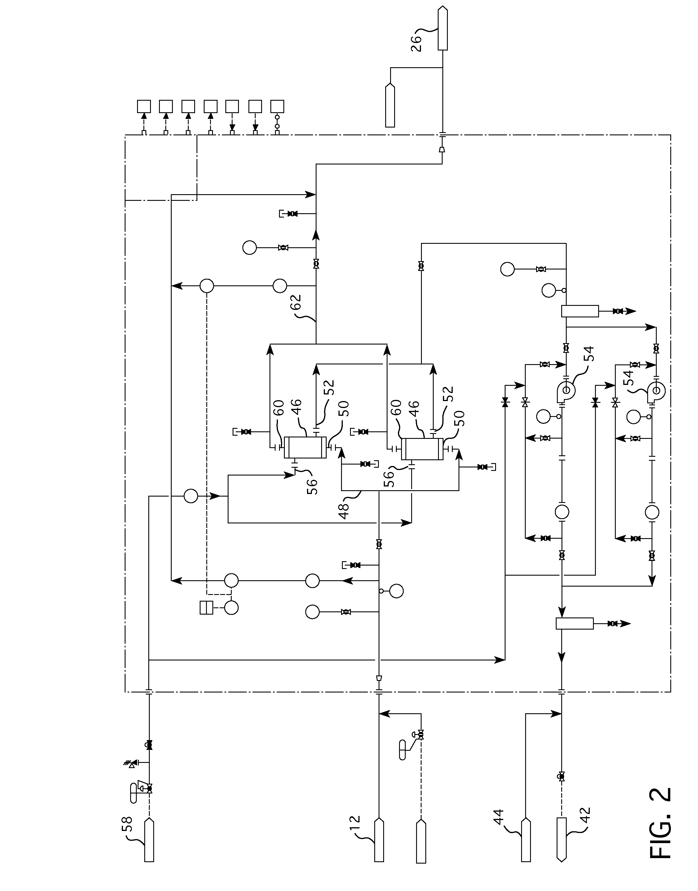
[0018]In accordance with this invention, one or more alternate “contactors” which respectively house a gas membrane are aligned in series and / or parallel, as required to handle the desired flow and the degree of gas removal. Liquid containing primarily dissolved hydrogen and the radioactive gases, i.e., xenon and krypton, enters the contactors at a relatively low pressure and exits the membranes degassed to the desired level. A vacuum is applied to ...


PUM


Abstract

An in-line dissolved gas removal membrane-based apparatus for removing dissolved hydrogen and fission gases from the letdown stream from a reactor coolant system.

Description

BACKGROUND[0001]1. Field[0002]The present invention relates generally to a process for removing dissolved gasses from reactor coolant in a nuclear power plant and more particularly to apparatus for removing dissolved hydrogen and fission gases from the reactor coolant by passing the coolant over a membrane and extracting the gasses by applying a vacuum.[0003]2. Related Art[0004]During pressurized water reactor plant shutdowns, it is a common practice to drain the reactor coolant system to a level below the reactor vessel flange to the mid-plane of the reactor vessel coolant outlet nozzles. That mid-plane coincides with the mid-plane of the connecting “hot leg” piping leading to the steam generators. This drain-down permits inspection, testing and maintenance, during shutdown, of pumps, steam generators, support structures and other primary system components.[0005]During reactor operation, some fission gases, e.g., xenon and krypton, created by the fission reactions occurring in the ...

Claims


Application Information

Patent Timeline
Patent Type & Authority Applications(United States)
IPC IPC(8): G21C19/303
CPCG21C19/303B01D19/0036G21C19/307G21F9/02G21C19/207Y02E30/30Y02E30/00B01D53/22G21D3/00G21F9/00B01D19/0031G21C15/00G21F9/06
Inventor CORPORA, GARY J.
Owner WESTINGHOUSE ELECTRIC CORP
Why Eureka
Try Eureka