Multipole Lens and Charged Particle Beam System

a technology of charged particle beam and multi-pole lens, which is applied in the direction of basic electric elements, electric discharge tubes, electrical equipment, etc., can solve the problems of complex wiring and terminal treatment, multi-pole lens noise, etc., and achieve the effect of simple structur

Active Publication Date: 2016-08-04
JEOL LTD
View PDF1 Cites 3 Cited by
  • Summary
  • Abstract
  • Description
  • Claims
  • Application Information

AI Technical Summary

Benefits of technology

[0030]This charged particle beam system can include a multipole lens which is simple in structure but cap

Problems solved by technology

Furthermore, variations in the currents flowing through the coils 120 give rise to deflecting fields and so

Method used


Image

  • Multipole Lens and Charged Particle Beam System
  • Multipole Lens and Charged Particle Beam System
  • Multipole Lens and Charged Particle Beam System

Examples


Embodiment Construction

[0037]The preferred embodiments of the present invention are hereinafter described in detail with reference to the drawings. It is to be understood that the embodiments provided below do not unduly restrict the scope and content of the present invention delineated by the appended claims and that not all the configurations described below are essential constituent components of the invention.

1. Multipole Lens

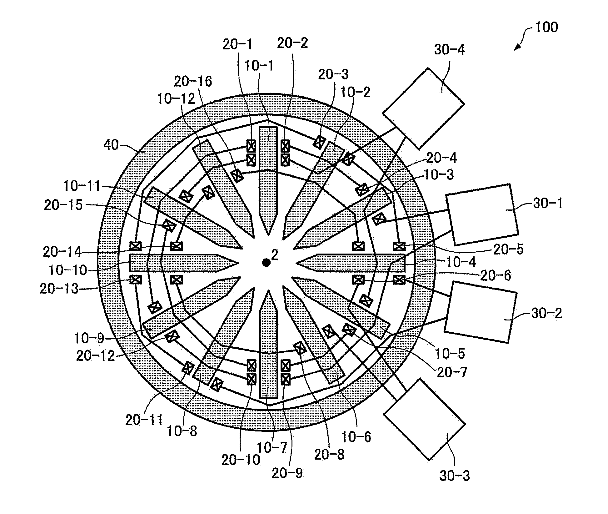
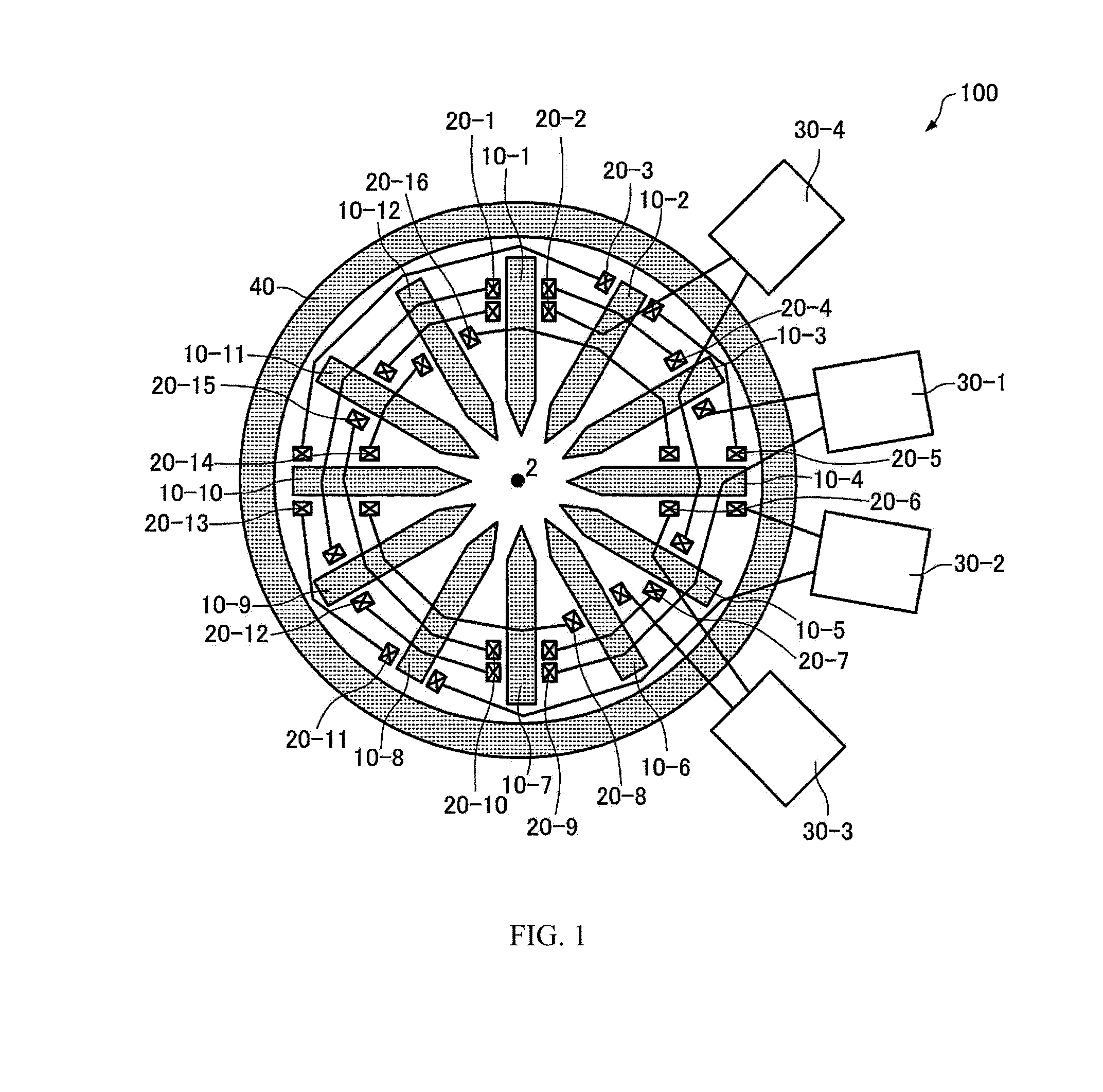
[0038]A multipole lens associated with one embodiment of the present invention is first described by referring to FIG. 1, which schematically shows the multipole lens, generally indicated by reference numeral 100. This multipole lens 100 includes first through twelfth polar elements (magnetic polepieces) 10-1 to 10-12, first through sixteenth coils 20-1 to 20-16, first through fourth power supplies 30-1 to 30-4, and a yoke 40.

[0039]The first through twelfth polar elements 10-1 to 10-12 are arranged in rotational symmetry about the optical axis 2 of the multipole lens 100. In the ...


PUM


Abstract

A multipole lens is provided which is for use in electron microscopy and which is simple in structure but capable of producing X- and Y-components of a quadrupole field and X- and Y-components of an octopole field. The multipole lens (100) comprises: first through twelfth polar elements (10-1 to 10-12); first through sixteenth coils (20-1 to 20-16); a first power supply (30-1) for supplying currents to the coils (20-1, 20-4, 20-9, 20-12); a second power supply (30-2) for supplying currents to the coils (20-3, 20-5, 20-11, 20-13); a third power supply (30-3) for supplying excitation currents to the coils (20-6, 20-8, 20-14, 20-16); and a fourth power supply (30-4) for supplying excitation currents to the coils (20-2, 20-7, 20-10, 20-15). The coils (20-1, 20-3, 20-6, 20-7, 20-9, 20-11, 20-14, 20-15) produce magnetic fields in a first direction. The coils (20-2, 20-4, 20-5, 20-8, 20-10, 20-12, 20-13, 20-16) produce magnetic fields in a direction opposite to the first direction.

Description

BACKGROUND OF THE INVENTION[0001]1. Field of the Invention[0002]The present invention relates to a multipole lens and also to a charged particle beam system.[0003]2. Description of Related Art[0004]In recent years, there have been known charged particle beam systems such as a transmission electron microscope (TEM) and a scanning electron microscope (SEM) each equipped with an aberration corrector for correcting aberrations. Aberration correctors operate to correct aberrations by applying a magnetic field, an electric field, or a superimposition of these fields to a passage for a charged particle beam (such as an electron beam) by the use of multipole lenses (see, for example, JP-A-2005-302405).[0005]For example, octopole fields are used for corrections of four-fold astigmatism and spherical aberration. In some cases, a low-order multipole field is superimposed on an octopole field to reduce the effects of axial deviation. In the case of a dodecapole lens, X- and Y-components of a qu...

Claims


Application Information

Patent Timeline
IPC IPC(8): H01J37/141
CPCH01J2237/141H01J37/141H01J2237/26
Inventor KOHNO, YUJI
Owner JEOL LTD
Why Eureka
Try Eureka