

Ion pump and charged particle beam device using the same
a technology of ion pump and charge particle, which is applied in the direction of electrical discharge tubes, particle separator tubes, electrical equipment, etc., can solve the problems of high cost, complex and large devices, and inability to obtain extreme high vacuum when ion pump is used alon
- Summary
- Abstract
- Description
- Claims
- Application Information
AI Technical Summary
Benefits of technology
Problems solved by technology
Method used
Image

Examples
embodiment 1
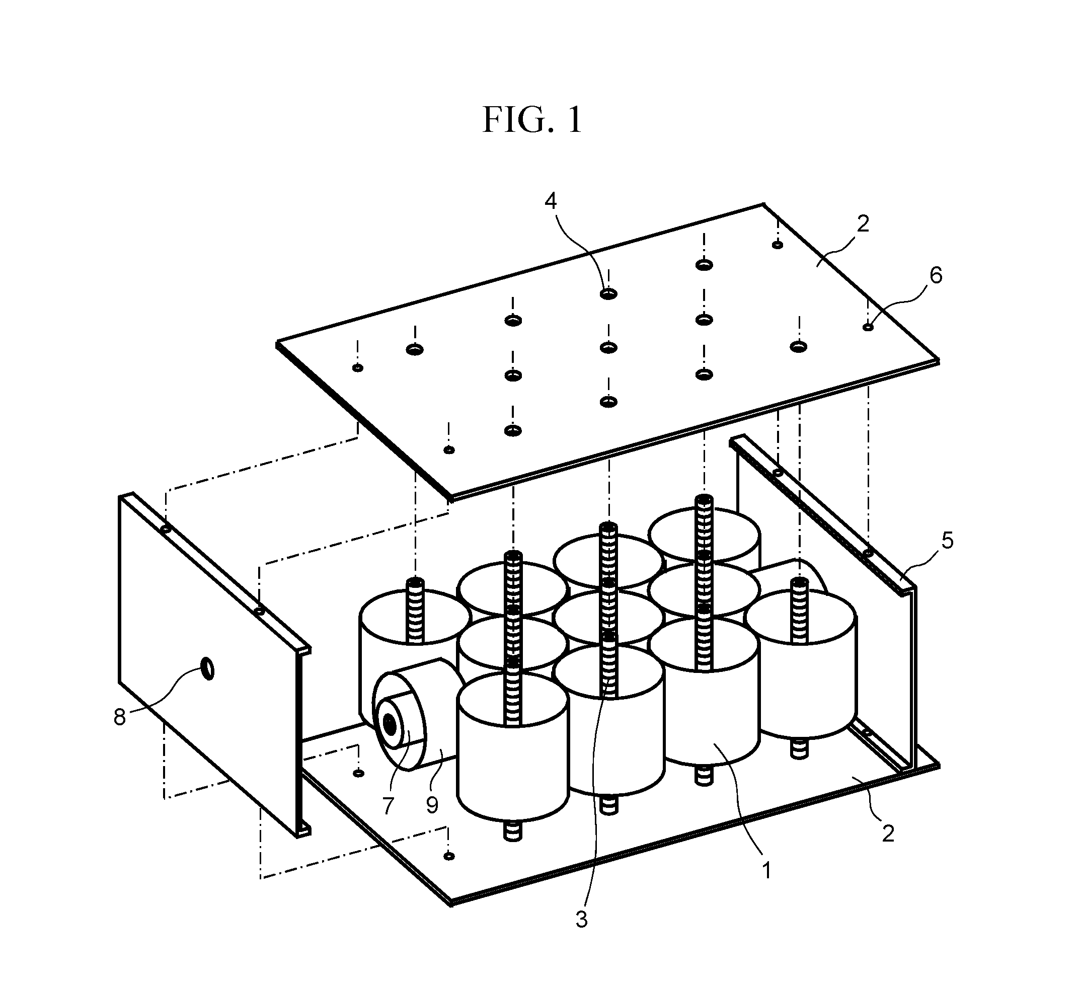
[0038]FIG. 1 is a perspective view showing elements of an ion pump in accordance with the present invention. The dashed-dotted line shows the mounting position of each component during assembly. The ion pump elements in FIG. 1 include an anode 1 having a plurality of cylindrical cells, two flat-plate cathodes 2 that are arranged along a direction in which openings of the anode 1 face, so as to sandwich the anode 1 therebetween, and cathode bars 3 that are arranged coaxially with the respective cylindrical cells. The flat-plate cathodes 2 and the cathode bars 3 are fixed together with bolts (not shown) screwed into fastening holes 4. Between the two flat-plate cathodes 2 are provided side walls 5 that are fixed thereto with bolts screwed into fastening holes 6.
[0039]The anode 1 has a configuration in which a plurality of cylindrical cells is welded and arranged. In order to arrange as many cylindrical cells as possible within the limited volume of the pump and increase the pumping sp...
embodiment 2
[0081]Embodiment 2 will describe a configuration example of the cathode bar 3 different from that in Embodiment 1. As the other configurations are the same as those in Embodiment 1, the configuration of the cathode bar 3 will be mainly described below.
[0082]FIG. 10 is a perspective view showing a configuration example of the cathode bar 3 in Embodiment 2. In the configuration example shown in FIG. 10, the cathode bar 3 is formed of a strand cathode 40 obtained by twisting linear NEG constituents 12. The materials of the NEG constituents 12 are the same as those in Embodiment 1. The opposite ends of the strand cathode 40 are fixed to the respective flat-plate cathodes 2, and the strand cathode 40 is arranged along the central axis of the cylindrical cell 23. When the strand cathode 40 is sputtered by ions of the residual gas 27, atoms of each of the linear NEG constituents 12 deposit on the inner wall of the cylindrical cell 23 and the surfaces of the flat-plate cathodes 2, so that t...
embodiment 3
[0087]Embodiment 3 of the present invention will describe configuration examples of an ion pump with an electron source. The other configurations are the same as those in Embodiments 1 to 2. Therefore, the configuration of the electron source will be mainly described hereinafter.
[0088]FIG. 13 is a side sectional view of the ion pump in accordance with Embodiment 3. As the cathode bar 3, the configuration shown in FIG. 11 is used as an example. In the configuration example shown in FIG. 13, some of the cathode bars 3 are removed, and a thermionic source 50 is provided in the cylindrical cell 23. As the material of the thermionic source 50, a material with a high melting point and a low sputtering rate, such as a tungsten filament, is used. The thermionic source 50 is arranged along the central axis of the cylindrical cell 23, and the opposite ends of the thermionic source 50 are fixed to the top and bottom flat-plate cathodes 2. The opposite ends of the thermionic source 50 are cover...
PUM
 Abstract
Description
Claims
Application Information