Adjustable cable voltage compensation for battery chargers

a battery charger and voltage compensation technology, applied in the field of switch mode power supply (smps), can solve the problems unable to provide different compensation for charging cables, and not cost-effective compensation methods that add compensation voltages to reference voltages, so as to avoid costly rework of controller ic, the effect of increasing design complexity and system cos

Active Publication Date: 2016-08-18
BCD SHANGHAI MICRO ELECTRONICS CO LTD
View PDF7 Cites 17 Cited by
  • Summary
  • Abstract
  • Description
  • Claims
  • Application Information

AI Technical Summary

Benefits of technology

[0007]The inventors observed that conventional methods of compensating for charging cable voltage drop have many drawbacks. For example, the conventional compensation method that adds a compensation voltage to a reference voltage is not desirable, because it requires additional electronic elements and is not cost-effective. The additional compensation circuitry may require several revisions of the controller IC to calibrate to the charging cable. Further, the compensation is fixed by the circuit and cannot provide different compensation for different charging cables. In embodiments of the invention, the compensation is adjusted by adjusting the value of a resistor external to the controller IC. As a result, costly rework of the controller IC can be avoided, and the same controller IC can be calibrated to work with different charging cables. Some conventional methods provide adjustable compensation, but require an extra pin to be added to the controller IC, increasing design complexity and system cost. In embodiments of the invention, no extra pin is needed, because the adjustment resistor is connected to an existing pin of a standard package for controller IC. Alternatively, the resistor may be part of a standard power supply circuitry, eliminating the need for the extra adjustment resistor, further reducing system complexity and cost.
[0009]According to an embodiment of the invention, a battery charger controller introduces a current source in the feedback control loop such that the output voltage varies with the output current to compensate for charging cable voltage drop. In some embodiments, a portion of the output voltage is also proportional to the resistance of a compensation resistor that is external to the controller IC. Therefore, cable voltage drop compensation can be easily adapted using the resistor. In an embodiment, the adjustable resistor outside the controlling IC may be one of the feedback resistors connected at a voltage feedback pin, and no additional component is required. In another embodiment, the adjustable resistor is a resistor between the feedback resistors and the voltage feedback pin. In still another embodiment, the adjustable resistor is a resistor in parallel with a compensation capacitor. In embodiments of the invention, adjusting the resistance of the compensation resistor can change the voltage drop compensation and allow the power supply to meet requirements of different charging cable applications.

Problems solved by technology

For example, the conventional compensation method that adds a compensation voltage to a reference voltage is not desirable, because it requires additional electronic elements and is not cost-effective.
Further, the compensation is fixed by the circuit and cannot provide different compensation for different charging cables.
Some conventional methods provide adjustable compensation, but require an extra pin to be added to the controller IC, increasing design complexity and system cost.

Method used


Image

  • Adjustable cable voltage compensation for battery chargers
  • Adjustable cable voltage compensation for battery chargers
  • Adjustable cable voltage compensation for battery chargers

Examples


Embodiment Construction

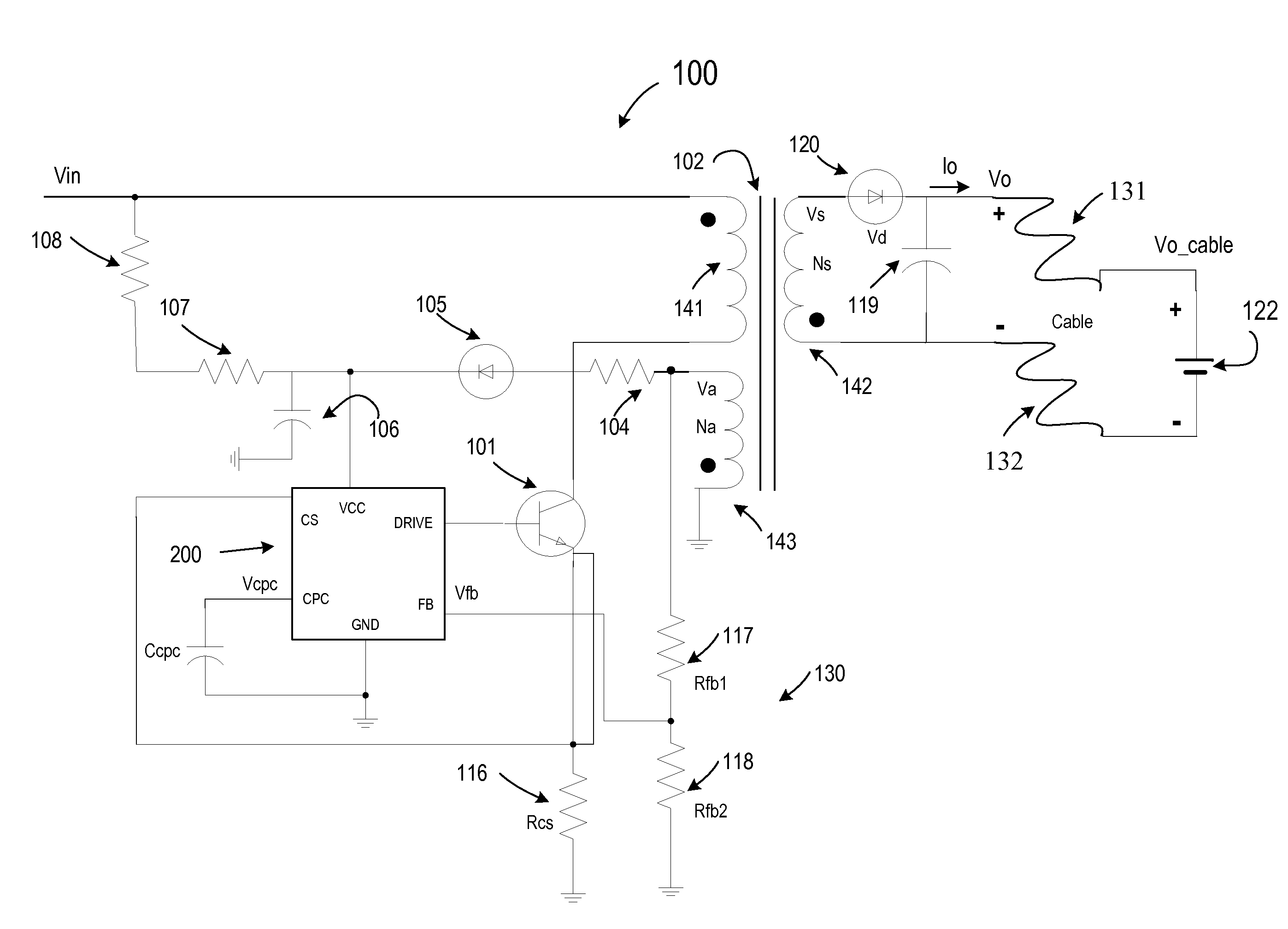
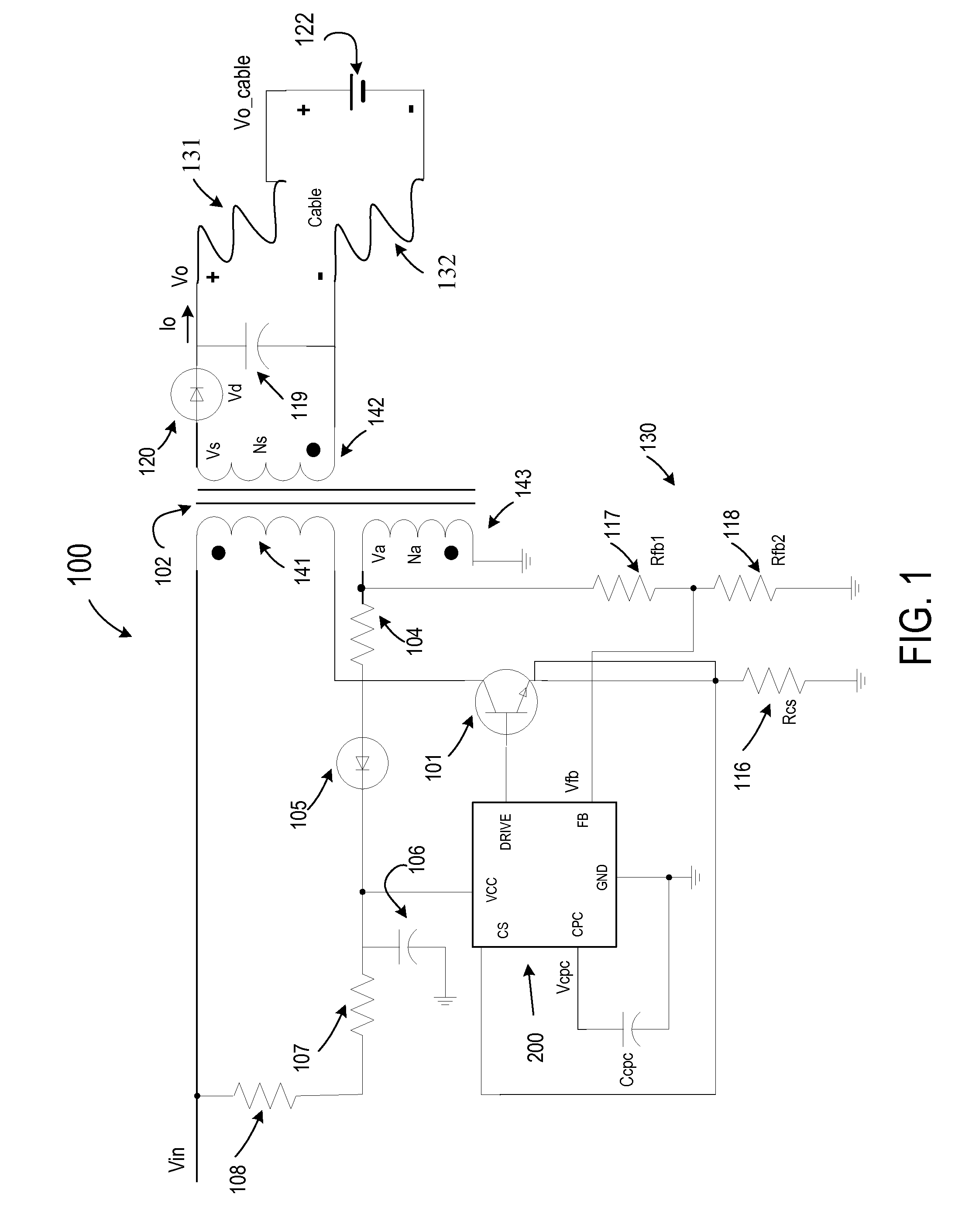
[0023]Embodiments of the present invention provide compensation methods to compensate the IR (current-resistance) voltage drop of charging cable to achieve accurate voltage control at the output cable terminal. The compensation can be adjusted for different charging cables by varying the resistance of a resistor external to the controller integrated circuit.

[0024]FIG. 1 is a simplified schematic diagram of a battery charging system according to an embodiment of the present invention. The battery charging system includes a primary-side regulated power supply 200, a battery 122, and charging cables 131 and 132, which connect battery 122 to the power supply. As shown in FIG. 1, the output voltage at the output terminals of the power supply is Vo, and the voltage at the terminals of the battery 122 is Vo_cable.

[0025]Switched mode power supply (SMPS) 100 includes a transformer 102, which includes a primary winding 141 for coupling to an input voltage Vin and a secondary winding 142 for p...


PUM


Abstract

A battery charger controller is configured to add a compensation current in the feedback control loop such that the output voltage varies with the output current to compensate charging cable voltage drop. In some embodiments, the output voltage is also proportional to a compensation resistor. Therefore, cable voltage drop compensation can be adjusted using a resistor that is external to the controller IC. The external resistor may be one of the feedback resistors connected at a voltage feedback pin. In another embodiment, the adjustable resistor is the resistor between the feedback resistors and the voltage feedback pin. In still another embodiment, the adjustable resistor is the resistor in parallel with a compensation capacitor. In embodiments of the invention, adjusting the resistance of the external compensation resistor can change the voltage drop compensation and allow the power supply to meet requirements of different charging cable applications.

Description

CROSS-REFERENCES TO RELATED APPLICATIONS[0001]This application claims priority to Chinese Patent Application No. 201410035354.X, filed Jan. 24, 2014, commonly owned and incorporated by reference herein.BACKGROUND OF THE INVENTION[0002]The present invention relates generally to the field of switch mode power supply (SMPS). More particularly, embodiments of the present invention relate to SMPS used as battery chargers that can be adapted to compensate for voltage drops from different charging cables.[0003]Switching power supply products have been widely used because of their small size, light weight, and high power conversion efficiency. For example, they are used in industrial automation and control, military equipment, scientific equipment, LED lighting, industrial equipment, communications equipment, electrical equipment, instrumentation, medical equipment, semiconductor cooling and heating, air purifiers, electronic refrigerator, LCD display, audio-visual products, security, compu...

Claims


Application Information

Patent Timeline
Patent Type & Authority Applications(United States)
IPC IPC(8): H02J7/00H02M3/335
CPCH02J7/0052H02J7/0072H02M3/33507H02J2207/20H02J7/02H02J7/007182H02J7/00711H02J7/00H02J7/0071
Inventor ZHAO, JINGJINGSU, QINGHUAWANG, HU
Owner BCD SHANGHAI MICRO ELECTRONICS CO LTD
Why Eureka
Try Eureka