
Energy supply circuit without power converter and electronic device using same

Active Publication Date: 2016-08-25
SEOUL NAT UNIV R&DB FOUND +1
View PDF2 Cites 6 Cited by
  • Summary
  • Abstract
  • Description
  • Claims
  • Application Information

AI Technical Summary

Benefits of technology

The invention provides an electronic circuit and energy supply circuit with no power converter or energy storage device, which has a simple structure, low manufacturing costs, and no energy loss due to power conversion. It also has no reduction in life due to charging and discharging of an energy storage device.

Problems solved by technology

Research into supplying energy using natural energy such as sunlight, solar heat, and wind power is being actively conducted due to issues of air pollution and fossil fuel exhaustion.
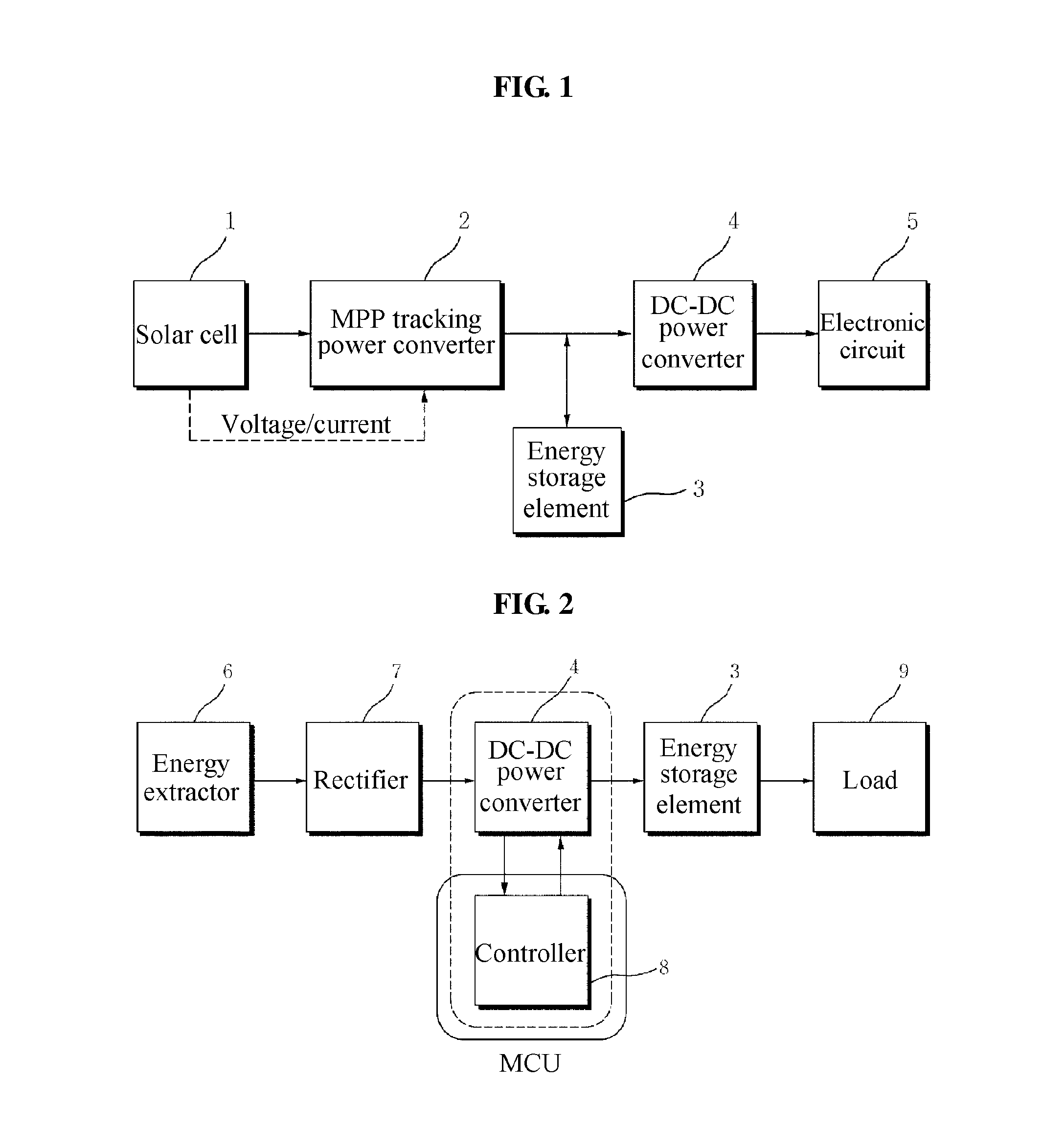
Concisely, the conventional sunlight supply apparatus includes the MPP tracking power converter 2 and the DC-DC power converter 4, and thus issues of increasing volume and manufacturing costs of the sunlight supply apparatus may arise.
Such issues may arise when a power converter is included, in relation to generation that may not be limited to sunlight generation.
A power converter is also a required part of the energy supply apparatus of FIG. 2, and thus the issues of increasing volume and manufacturing costs of the energy supply apparatus may arise.

Method used


Image

  • Energy supply circuit without power converter and electronic device using same
  • Energy supply circuit without power converter and electronic device using same
  • Energy supply circuit without power converter and electronic device using same

Examples


first embodiment

[0033]The first embodiment of the electronic circuit has a structure in which the energy extractor 10 of the energy supply circuit 100 is a photovoltaic cell (PV cell), and the microprocessor 60 is included in the external electronic circuit 200. The external electronic circuit 200 may further include a ROM 62, a clock generator 64, and a peripheral device 66.

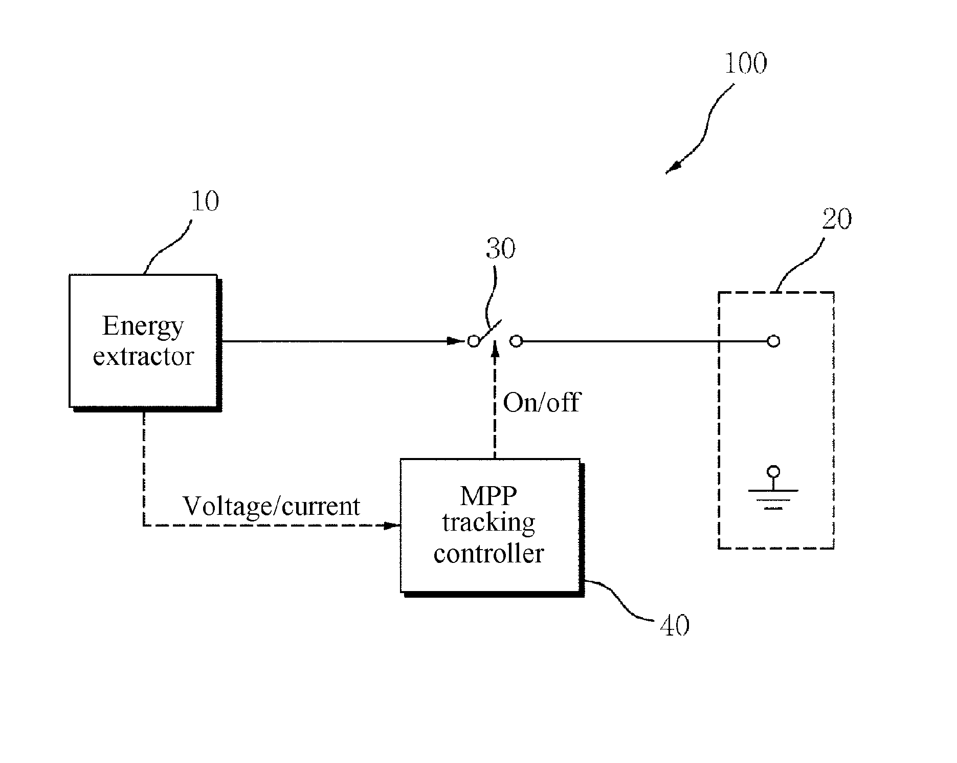
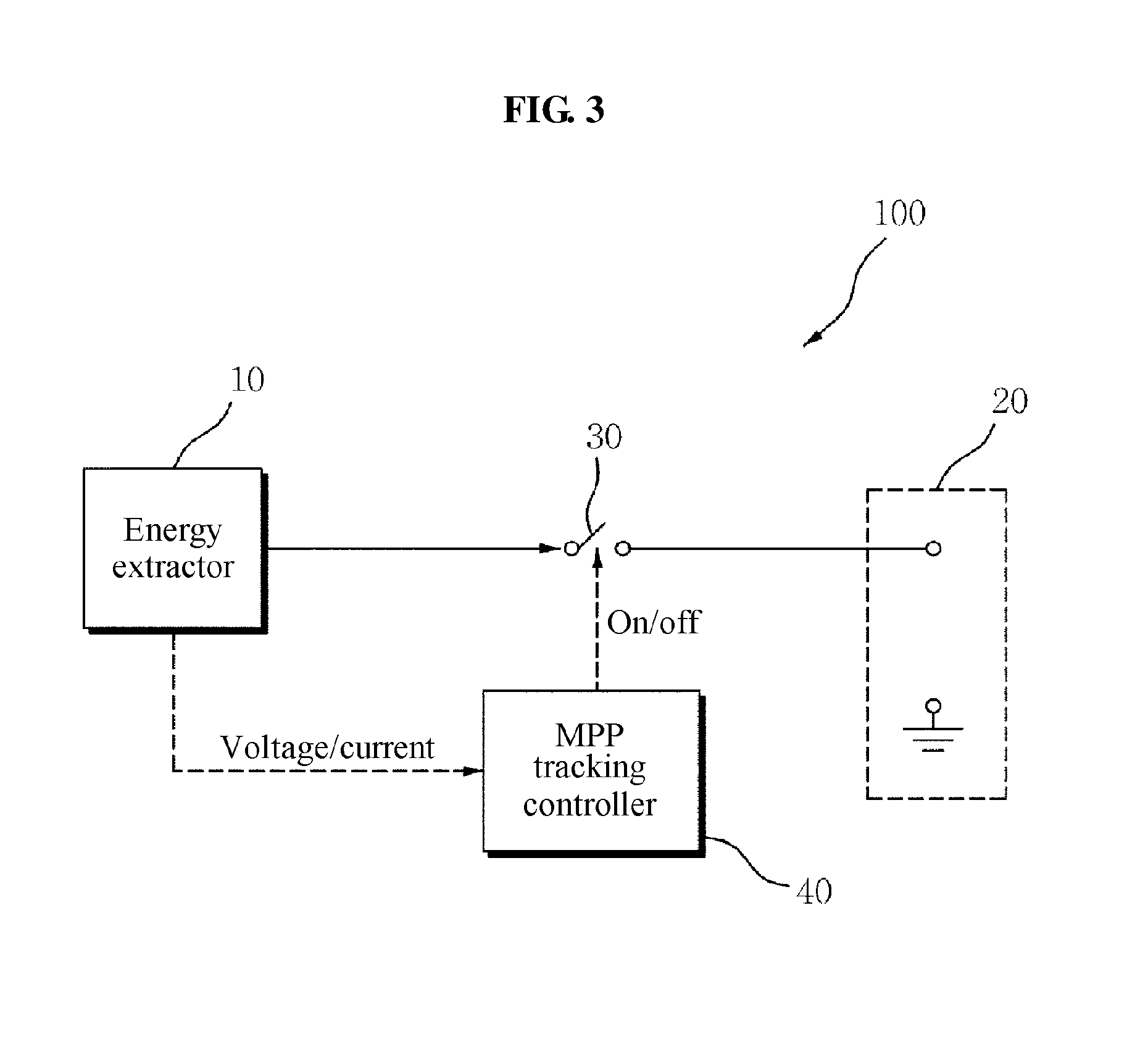
[0034]FIG. 5 illustrates an electronic device according to a first embodiment of the present invention. According to the first embodiment, the energy extractor 10 is a solar cell 14, the switch 30 is a field effect transistor 32, and the MPP controller 40 provides an on and off signal on which pulse width modulation (PWM) is performed for a gate of the field effect transistor 32 according to a voltage and a current (being subordination variables of an external environment, for example, a temperature and irradiance) of the solar cell 14. Thus, as the external environment is changed, MPP tracking control by dynamic power manageme...

second embodiment

[0051]In a second embodiment of the present invention, the energy extractor 10 of the energy supply circuit 100 is the solar cell 14, and the external electronic circuit 200 is an ultraviolet index displaying circuit.

[0052]FIG. 10 illustrates an electronic device according to a second embodiment of the present invention. The energy supply circuit 100 is identical to that of the first embodiment, and the external electronic circuit 200 includes an ultraviolet sensor 70, a microprocessor 60, for example, a microprocessor unit (MPU), and a display 80. Based on a type of the ultraviolet sensor 70, an AD converter may be disposed between the ultraviolet sensor 70 and the microprocessor 60. It is advisable to provide the display 80 as a low power liquid crystal display (LCD). The electronic device illustrated in FIG. 9 may be produced as a slim electronic device at low cost, such that the electronic device may be provided as a patch attached to an inside of a vehicle or a sunscreen contai...

third embodiment

[0054]In a third embodiment of the present invention, the energy extractor 10 of the energy supply circuit 100 is a piezoelectric element 16, and the external electronic circuit 200 is a weight measurement circuit.

[0055]FIG. 12 illustrates an electronic device according to a third embodiment of the present invention. In the energy supply circuit 100, the energy extractor 10 is replaced with the piezoelectric element 16 from the solar cell 14, and the external electronic circuit 200 includes the microprocessor 60 and the display 80. In the third embodiment, the piezoelectric element 16 may supply energy to the energy extractor 10 and provide pressure information or weight information to the microprocessor 60 at the same time.

[0056]In the second embodiment and the third embodiment, the external electronic circuit 200 may process information, for example, an ultraviolet index and a weight, on an object to be supplied the energy, thereby increasing efficiency of the electronic device. I...


PUM


Abstract

The present invention relates to an energy supply circuit for instantly supplying power without a power converter and an electronic device which operates only when energy is supplied from an energy source using the same. An energy supply circuit without a power converter according to the present invention comprises: an energy extraction unit 10 for generating power from an energy source; and output unit 20 for supplying power to an external electronic circuit; a switch unit 30 interposed between the energy extraction unit and the output unit 20 to connect an output end of the energy extraction unit 10 to the output unit 20 when switched on; and a maximum power point tracking control unit 40 for generating an open / closed signal for opening or closing the switch unit 30 according to the voltage and current of the energy extraction unit 10. The present invention has a technical feature wherein a turn-on point of the open / closed signal comes at a time when the output end voltage of the energy extraction unit 10 is Vh, and a turn-off point comes at a time when the output end voltage of the energy extraction unit 10 is Vl. Accordingly, the present invention has a simple configuration, low manufacturing costs, has no energy loss due to the power conversion, and has no reduction in life due to charging and discharging of an energy storage device.

Description

TECHNICAL FIELD[0001]The present invention relates to an energy circuit without a power converter and an electronic device using the same, and more particularly, to an energy supply circuit for tracking a maximum power point (MPP) without a power converter and an electronic device operating only when an energy is supplied from an energy source using the same.BACKGROUND ART[0002]Research into supplying energy using natural energy such as sunlight, solar heat, and wind power is being actively conducted due to issues of air pollution and fossil fuel exhaustion. Since an amount of sunlight as an energy source is limitless, a required amount of the sunlight is produced in a required place, and maintaining the sunlight is relatively easy. Thus, the sunlight may be used for various uses of an energy supply apparatus. In general, a sunlight energy supply apparatus may track a maximum power point (MPP) to extract a maximum power. An example of such conventional sunlight energy supply apparat...

Claims


Application Information

Patent Timeline
IPC IPC(8): G05F5/00G01G23/36
CPCG05F1/67G05F5/00G01G23/36B60L1/00G06F1/30Y02E10/50G05F1/66
Inventor CHANG, NAE-HYUCKYANG, JIN-YOUNGRIM, CHAI-YEOIKYUNG, CHONG-MIN
Owner SEOUL NAT UNIV R&DB FOUND
Learn More