Dynamic tag compare circuits employing p-type field-effect transistor (PFET)-dominant evaluation circuits for reduced evaluation time, and related systems and methods

a field-effect transistor and evaluation circuit technology, applied in the field of dynamic logic circuits, can solve problems such as and achieve the effects of reducing transistor gate capacitance, reducing evaluation time, and reducing the effective mass of charge carriers

Inactive Publication Date: 2016-08-25
QUALCOMM INC
View PDF9 Cites 1 Cited by
  • Summary
  • Abstract
  • Description
  • Claims
  • Application Information

AI Technical Summary

Benefits of technology

[0008]Aspects of the disclosure involve dynamic tag compare circuits employing P-type Field-Effect Transistor (PFET)-dominant evaluation circuits for reduced evaluation time. Related systems and methods are also disclosed. Dynamic logic circuits may be provided in a processor to perform logic operations as one example. Dynamic logic circuits are usually faster than static logic circuit counterparts, because dynamic logic circuits reduce transistor gate capacitance during a logic evaluation. Since circuit delay is directly proportional to output capacitance, the delay of a dynamic logic circuit is conventionally lower than a static logic circuit. It has been observed that as node technology is scaled down in size, PFET drive current (i.e., drive strength) exceeds N-type FET (NFET) drive current for like-dimensioned FETs. This is due to the introduction of strained silicon in FET fabrication to reduce the effective mass of charge carriers.

Problems solved by technology

This is due to the introduction of strained silicon in FET fabrication to reduce the effective mass of charge carriers.

Method used


Image

  • Dynamic tag compare circuits employing p-type field-effect transistor (PFET)-dominant evaluation circuits for reduced evaluation time, and related systems and methods
  • Dynamic tag compare circuits employing p-type field-effect transistor (PFET)-dominant evaluation circuits for reduced evaluation time, and related systems and methods
  • Dynamic tag compare circuits employing p-type field-effect transistor (PFET)-dominant evaluation circuits for reduced evaluation time, and related systems and methods

Examples


Embodiment Construction

[0022]With reference now to the drawing figures, several exemplary aspects of the present disclosure are described. The word “exemplary” is used herein to mean “serving as an example, instance, or illustration.” Any aspect described herein as “exemplary” is not necessarily to be construed as preferred or advantageous over other aspects.

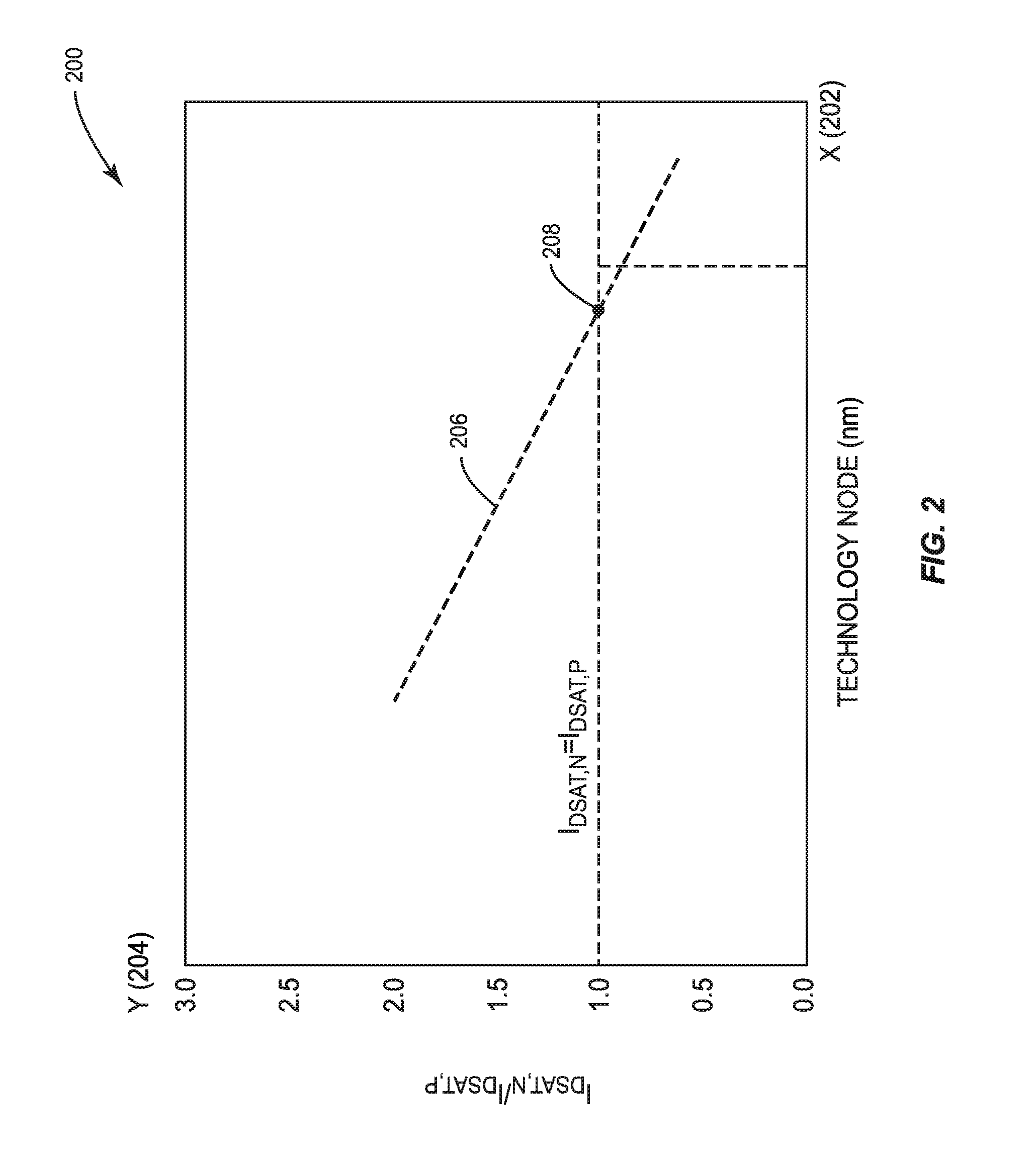
[0023]As shown in a graph 200 in FIG. 2, it has been observed that as node technology is scaled down in size, PFET drive current (i.e., drive strength) exceeds NFET drive current for like-dimensioned FETs. This is due to the introduction of strained silicon in FET fabrication to reduce the effective mass of charge carriers. As illustrated in FIG. 2, the technology node size in nanometers (nm) is provided on an X-axis 202. The ratio of the saturation drain current (IDSAT,N) of an NFET to saturation drain current (IDSAT,P) of a PFET is provided on a Y-axis 204. The ratio of IDSAT,N to IDSAT,P as a function of technology node size in nm is shown on a rat...


PUM


Abstract

Dynamic tag compare circuits employing P-type Field-Effect Transistor (PFET)-dominant evaluation circuits for reduced evaluation time, and thus increased circuit performance, are provided. A dynamic tag compare circuit may be used or provided as part of searchable memory, such as a register file or content-addressable memory (CAM), as non-limiting examples. The dynamic tag compare circuit includes one or more PFET-dominant evaluation circuits comprised of one or more PFETs used as logic to perform a compare logic function. The PFET-dominant evaluation circuits are configured to receive and compare input search data to a tag(s) (e.g., addresses or data) contained in a searchable memory to determine if the input search data is contained in the memory. The PFET-dominant evaluation circuits are configured to control the voltage / value on a dynamic node in the dynamic tag compare circuit based on the evaluation of whether the received input search data is contained in the searchable memory.

Description

PRIORITY APPLICATION[0001]The present application claims priority under 35 U.S.C. §119(e) to U.S. Provisional Patent Application Ser. No. 62 / 119,769 filed on Feb. 23, 2015 and entitled “P-TYPE FIELD-EFFECT TRANSISTOR (PFET)-DOMINANT DYNAMIC LOGIC CIRCUITS, AND RELATED SYSTEMS AND METHODS,” which is incorporated herein by reference in its entirety.BACKGROUND[0002]I. Field of the Disclosure[0003]The technology of the disclosure relates generally to dynamic logic circuits clocked by a clock signal, and more particularly to increasing speed performance of dynamic logic circuits.[0004]II. Background[0005]Dynamic logic circuits provide significant performance advantages in comparison to static logic circuits. Dynamic logic circuits reduce transistor gate capacitance during a logic evaluation. In this regard, as an example, a conventional processor contains many instances of dynamic logic circuits throughout its design in performance-critical logic to provide faster evaluation of logic eva...

Claims


Application Information

Patent Timeline
Patent Type & Authority Applications(United States)
IPC IPC(8): G11C15/04H03K19/003G11C11/40H03K19/094
CPCG11C15/04G11C11/40H03K19/00315H03K19/094
Inventor BOWMAN, KEITH ALANATALLAH, FRANCOIS IBRAHIMHANSQUINE, DAVID JOSEPH WINSTONJEONG, JIHOONNGUYEN, HOAN HUU
Owner QUALCOMM INC
Why Eureka
Try Eureka