Wavelength multiplexing transmission system

a transmission system and wavelength technology, applied in the field of wavelength multiplexing transmission systems, can solve the problems of limiting the power of transmission lights, increasing the spectral width of each transmission light, and increasing the cost of transmission equipment, so as to reduce the degradation of transmission characteristics and simple and low-cost configuration

Inactive Publication Date: 2016-09-01
MITSUBISHI ELECTRIC CORP
View PDF18 Cites 7 Cited by
  • Summary
  • Abstract
  • Description
  • Claims
  • Application Information

AI Technical Summary

Benefits of technology

[0016]Because the wavelength multiplexing transmission system according to the present invention is configured as above, the wavelength multiplexing transmission system can suppress degradation in the transmission characteristics with a simple and low-cost configuration.

Problems solved by technology

However, because a nonlinear effect of fibers occurs remarkably and this results in degradation in the transmission characteristics when the light power inputted to the optical fiber is increased, there is a limit to the transmission light power.
A problem is however that because the S / N ratio (Signal to Noise) is reduced when the transmission light power is decreased, the transmission characteristics get worse when the transmission light power is decreased too much.
Further, when the bit rate is increased, the spectral width of each transmission light becomes large.
Therefore, in the case of using OOK (ON-OFF Keying) or DPSK (Differential Phase Shift Keying) which is a conventional modulation method, there occurs a disadvantage of being unable to narrow the wavelength interval and hence gain a larger number of wavelengths to be multiplexed.
A problem with this configuration is however that the optical tunable filters 1052 and 1055 whose number is two times as large as the number of carriers and the two optical couplers 1053 and 1054 are needed in the transponder 105, and therefore the configuration is complicated and costs a lot.
Further, in a wavelength multiplexing transmission system using a conventional multi carrier method, as a cause of degradation in the transmission characteristics, there can be provided, for example, a lack in the balance of the spectrum at the time of wavelength multiplexing, the lack being caused by the occurrence of a difference among the light powers of the carriers, or an increase in the nonlinear penalty due to the long distance transmission, the increase being caused by the matching of the polarizations or the modulation timings of the carriers.

Method used


Image

  • Wavelength multiplexing transmission system
  • Wavelength multiplexing transmission system
  • Wavelength multiplexing transmission system

Examples


embodiment 1

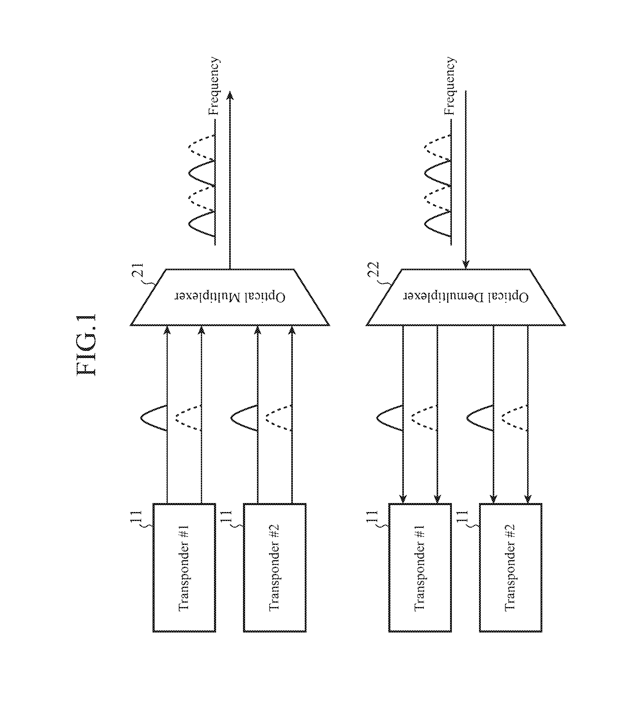
[0024]FIG. 1 is a diagram showing an outline of a wavelength multiplexing transmission system according to Embodiment 1 of the present invention.

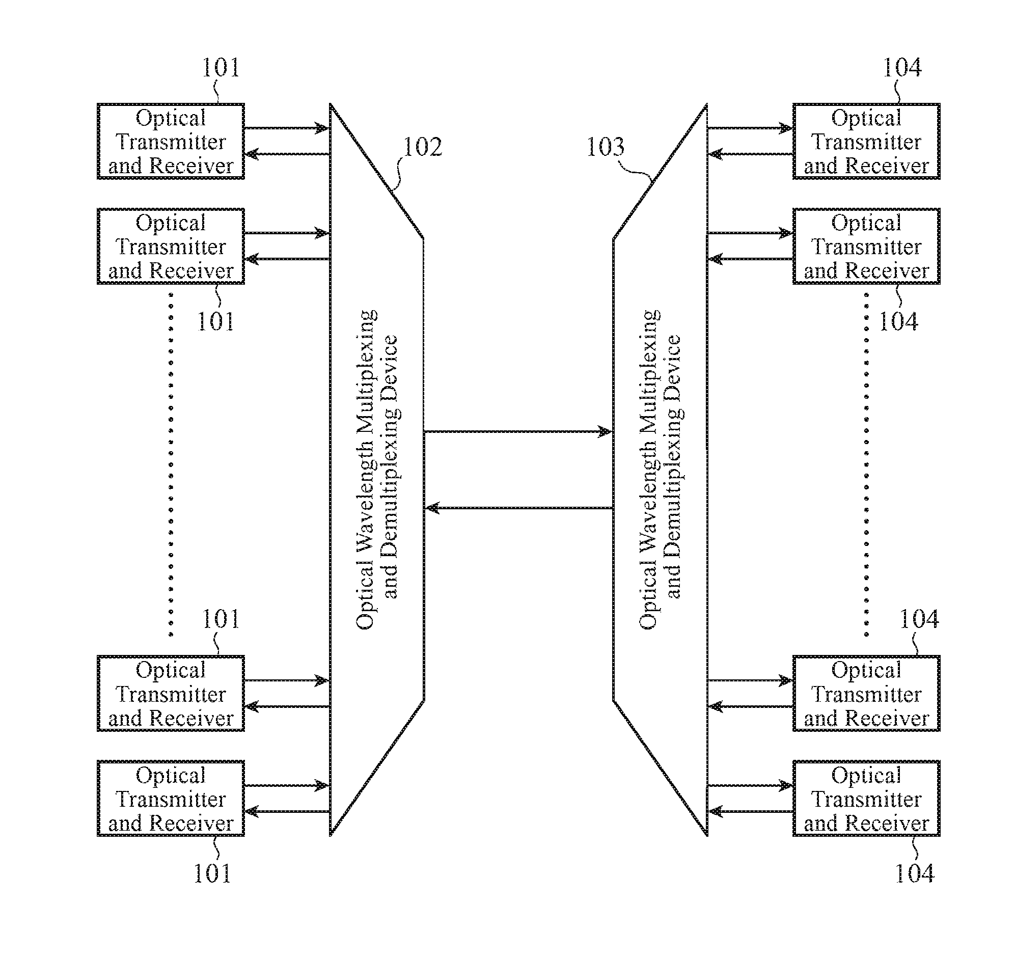
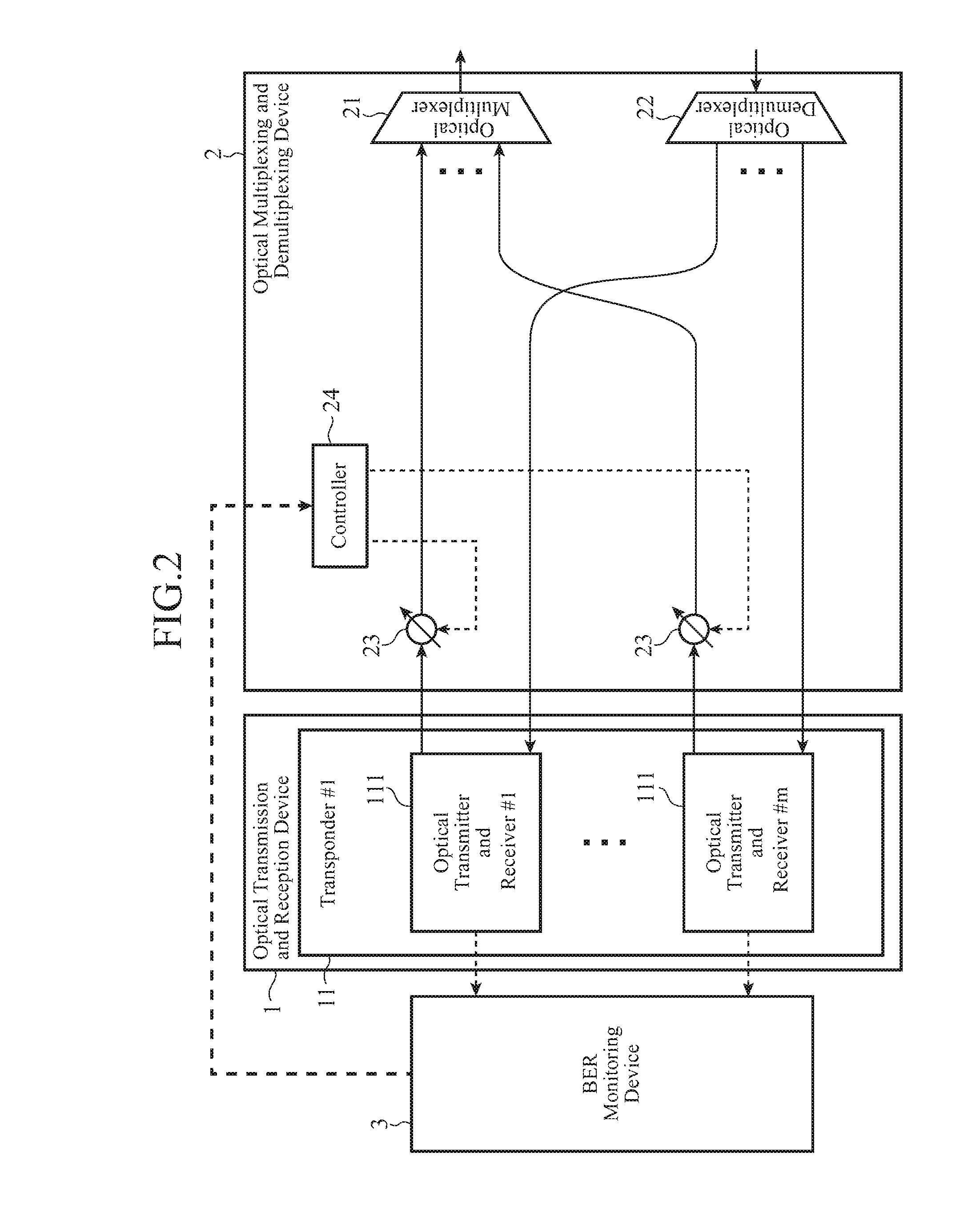
[0025]In the wavelength multiplexing transmission system according to the present invention, as shown in FIG. 1, a function of performing multiplexing / demultiplexing on carriers (light signals) is disposed in, not in each of transponders 11, but in an optical multiplexing and demultiplexing device 2 (an optical multiplexer 21 and an optical demultiplexer 22) disposed outside the transponders. As a result, there can be provided a simple and low-cost system having a configuration which, instead of employing twice as many tunable filters as the number of carriers, typical interleaver and AWG (Arrayed-Waveguide Gating) can be employed as an alternative.

[0026]Further, according to Embodiment 1, in order to prevent degradation in transmission characteristics due to a power difference among the carriers within the AWG, a function of monitoring the...

embodiment 2

[0044]In Embodiment 1, the case of having a function of, in order to prevent, degradation in the transmission characteristics due to a difference in power among the carriers within the AWG, monitoring the BER of each carrier and controlling the VOAs 23 in such a way that the sum total of the BERs becomes small is shown. In contrast with this, in Embodiment 2, a case of having a function of controlling the polarization of each of carriers so as to deviate the polarizations of the carriers from one another at equal intervals, thereby suppressing a nonlinear penalty will be shown.

[0045]FIG. 3 is a diagram showing the configuration of a wavelength multiplexing transmission system according to Embodiment 2 of the present invention. In FIG. 3, only the configuration of a transmit side, which is included in the configuration of the wavelength multiplexing transmission system, is illustrated. The wavelength multiplexing transmission system according to Embodiment 2 shown in FIG. 3 is a one ...

embodiment 3

[0049]In Embodiment 1, the case of having a function of, in order to prevent degradation in the transmission characteristics due to a difference in power among the carriers within the AWG, monitoring the BER of each carrier and controlling the VOAs 23 in such a way that the sum total of the BERs becomes small is shown. In contrast with this, in Embodiment 3, a case of having a function of monitoring the modulation timing of each of carriers and controlling the modulation timing so as to shift the modulation timings of the carriers relative to one another, thereby suppressing a nonlinear penalty will be shown.

[0050]FIG. 4 is a diagram showing the configuration of a wavelength multiplexing transmission system according to Embodiment 3 of the present invention. In FIG. 4, only the configuration of a transmit side, which is included in the configuration of the wavelength multiplexing transmission system, is illustrated. The wavelength multiplexing transmission system according to Embodi...


PUM


Abstract

A wavelength multiplexing transmission system including an optical transmission and reception device including a plurality of transponders each having a plurality of optical transmitters and receivers, a BER monitoring device to monitor the BERs of the optical transmitters and receivers, variable optical attenuators to attenuate light signals outputted from the optical transmitters and receivers, a controller to control the amounts of attenuation of the variable optical attenuators such that the sum total of the BERs of the optical transmitters and receivers becomes small, and an optical multiplexing and demultiplexing device to multiplex the light signals attenuated into a light signal and transmit this light signal to outside the system, and demultiplex a light signal from outside the system into light signals and transmit these light signals to the optical transmitters and receivers.

Description

FIELD OF THE INVENTION[0001]The present invention relates a wavelength multiplexing transmission system provided with an optical transmission and reception device having a plurality of transponders each having a plurality of optical transmitters and receivers.BACKGROUND OF THE INVENTION[0002]Optical submarine cable transmission systems are divided roughly into unrepeated transmission methods which are applied to cross-strait communications for a short distance, or the like, and repeated transmission methods which are applied to cross-ocean communications for a long distance, or the like. Typically, an optical submarine cable transmission system based on a relay transmission method is comprised of a submarine transmission line, coast station devices disposed on lands on both ends of the submarine transmission line, etc., and submarine repeaters are disposed at repeating spans of about 50 km in the submarine transmission line. In optical submarine cable transmission systems, a wavelen...

Claims


Application Information

Patent Timeline
Patent Type & Authority Applications(United States)
IPC IPC(8): H04B10/079H04J14/02H04J14/06
CPCH04B10/07953H04J14/0221H04J14/06H04B10/0799H04B10/564H04B10/674
Inventor HAYASHI, SHUSAKU
Owner MITSUBISHI ELECTRIC CORP
Why Eureka
Try Eureka