A device for detecting profile in refiner and method therefore

a technology of profile detection and refiner, which is applied in the direction of material impedance, instruments, papermaking, etc., can solve the problems of inconvenient use of temperature data, inconvenient measurement of fiber concentration and steam point, and large system size, so as to improve production rate, control the refiner performance, and cost-effective

Active Publication Date: 2016-09-08
DAPROKS AB
View PDF4 Cites 1 Cited by
  • Summary
  • Abstract
  • Description
  • Claims
  • Application Information

AI Technical Summary

Benefits of technology

[0011]It will thus be possible to control the refiner performance from detected fiber concentration and / or steam point. An user of the refiner can thus cost-effective perform automatic recalibrations during production and continuously correlate water amount inflow in-between the refiner discs, thereby controlling the position of the steam point in radial direction of the refiner discs. Such continuous measurement implied improved production rate as well.
[0012]The position of the steam point is important for cost-effective reaching the production of proper pulp quality and at the same time not unnecessary overloading of the refiner, which in turn involves high power consumption.

Problems solved by technology

However, there are still no efficient way to measure fiber concentration and steam point between refiner plates for reaching a high quality production at the same time energy saving process.
However, such systems are bulky and require complex software applications executing data from temperature sensors, motor loads, dilution water feeding rate, inlet temperature and pressure, material properties etc.
The use of temperature data is hazardous since the temperature per se does not indicate the refiner pad consistency and fiber concentration.

Method used


Image

  • A device for detecting profile in refiner and method therefore
  • A device for detecting profile in refiner and method therefore
  • A device for detecting profile in refiner and method therefore

Examples


Embodiment Construction

[0055]Hereinafter, embodiments of the present invention will be described in detail with reference to the accompanying drawings, wherein for the sake of clarity and understanding of the invention some details of no importance are deleted from the drawings.

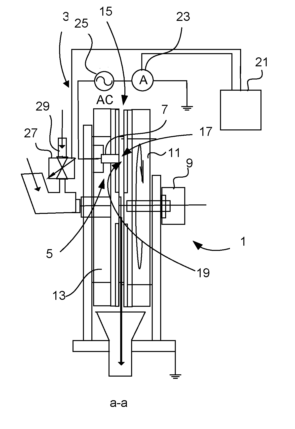
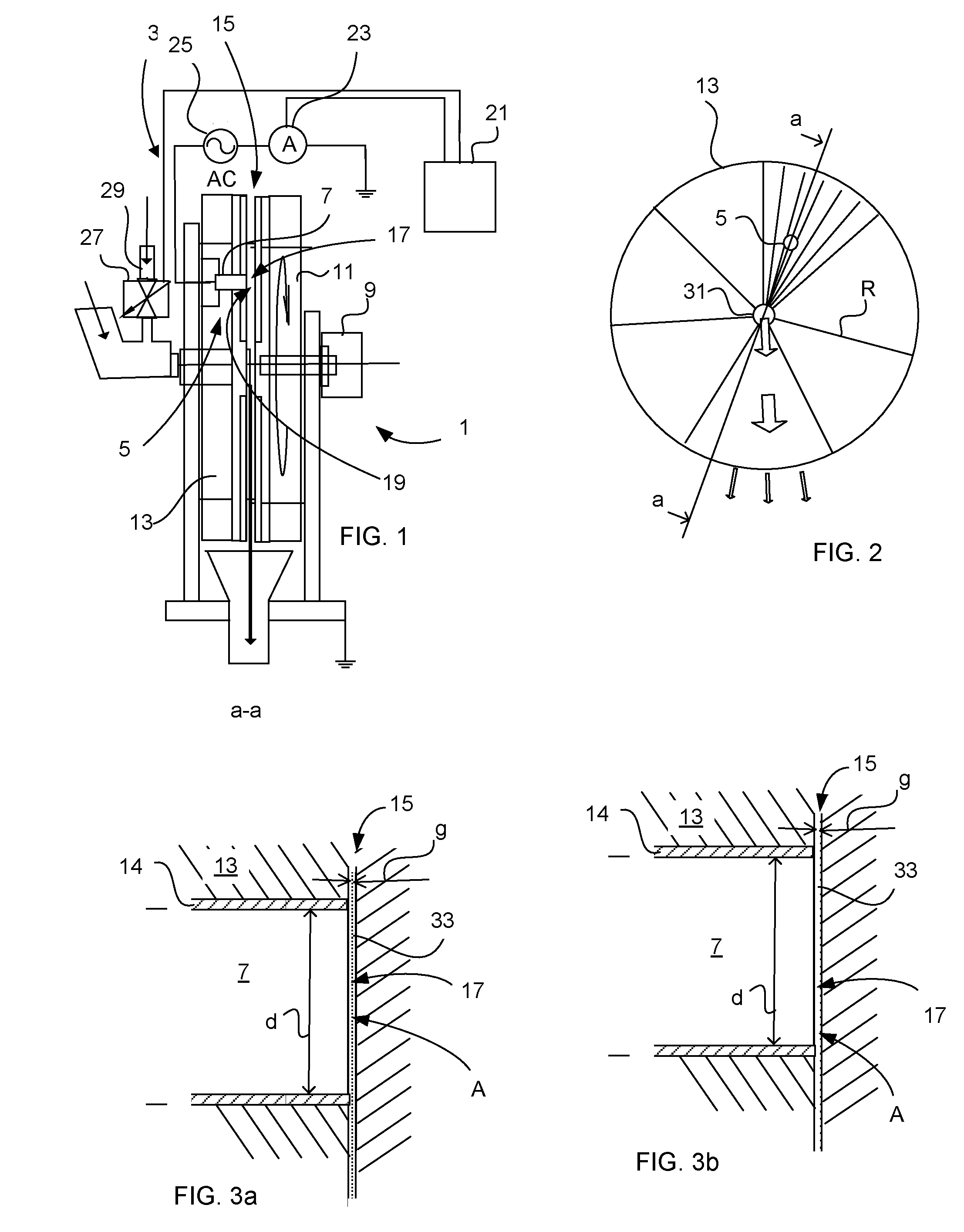
[0056]FIG. 1 illustrates a refiner 1 arranged for pulping a fiber pad into a pulp. The refiner 1 comprises a measuring device 3, comprising a sensor probe 5 including a conductor body 7 adapted to conduct an electric AC current. A motor 9 drives a rotor refiner disc 11. A stator refiner disc 13 is rigidly mounted to the refiner 1, in which disc 13 the sensor probe 5 is mounted. The refiner 1 comprises a grinding gap 15 provided between the refiner discs 11, 13. The conductor body 7 exhibiting a first electric contact surface 17, which is adapted to provide electrical contact with a second electric contact surface 19, which being constituted of the grinding surface of the opposite rotor refiner disc 11, for transferring an electric ...


PUM

PropertyMeasurementUnit
frequencyaaaaaaaaaa
frequencyaaaaaaaaaa
frequenciesaaaaaaaaaa

Abstract

The invention regards a measuring device, comprising a conductor body (7), for detecting the degree of fiber concentration and/or steam point (SP) of a fiber pad (33) being pulped, during use of the device (3), in a grinding gap (15) between refiner discs (11, 13) of a refiner (1). The conductor body (7) exhibits a first electric contact surface (17) adapted to provide electrical contact with a second electric contact surface (19) for transferring an electric current via the fiber pad (33) material. The invention also regards a method for detecting the degree of fiber concentration and/or steam point (SP) of a fiber pad (33). The method comprises the steps of mounting of the conductor body (7) to one of the refiner discs (13), grinding the fiber pad (33) material between the refiner discs (11, 13), detecting alteration of the conductivity and/or electrical resistivity of the fiber pad (33) material, and adjusting inflow of water and/or fiber material from said detected alteration.

Description

TECHNICAL FIELD[0001]The present invention relates to a measuring device according to the preamble of claim 1 and to a method according to claim 9.[0002]The invention regards refiners and pulp producing plants. It is associated with industry for making paper, fiber board's etc. It also relates to Research and Development projects having an object to improve energy efficiency in Thermo Mechanical Pulp TMP plants or similar.BACKGROUND ART[0003]There have been several attempts to improve the measurement of fiber concentration in a so called refiner zone of a fiber pad distribution being processed between mill plates (discs) of a refiner. New measurement techniques have been developed to keep the quality of the pulp as consistent as possible. Sensor means are mounted in refiners for measure of fiber concentration in the fiber pad. Paper making industry using refiners has interest in saving energy and there is a desire to balance energy consumption and fiber material refining process usi...

Claims


Application Information

Patent Timeline
Patent Type & Authority Applications(United States)
IPC IPC(8): G01N27/04G01N33/40G01N33/34
CPCG01N27/045G01N33/40G01N33/34D21D1/30G01N27/04G01N33/343D21B1/14G01N27/02
Inventor KERBLOM, BENGT
Owner DAPROKS AB
Why Eureka
Try Eureka