
A skin treatment device for multiphoton ionization-based skin treatment

a skin treatment and photon ionization technology, applied in the field of skin treatment devices, can solve the problem of challenging to achieve the multi-photon ionization process deep inside the skin

Inactive Publication Date: 2016-09-22
KONINKLJIJKE PHILIPS NV
View PDF0 Cites 21 Cited by
  • Summary
  • Abstract
  • Description
  • Claims
  • Application Information

AI Technical Summary

Benefits of technology

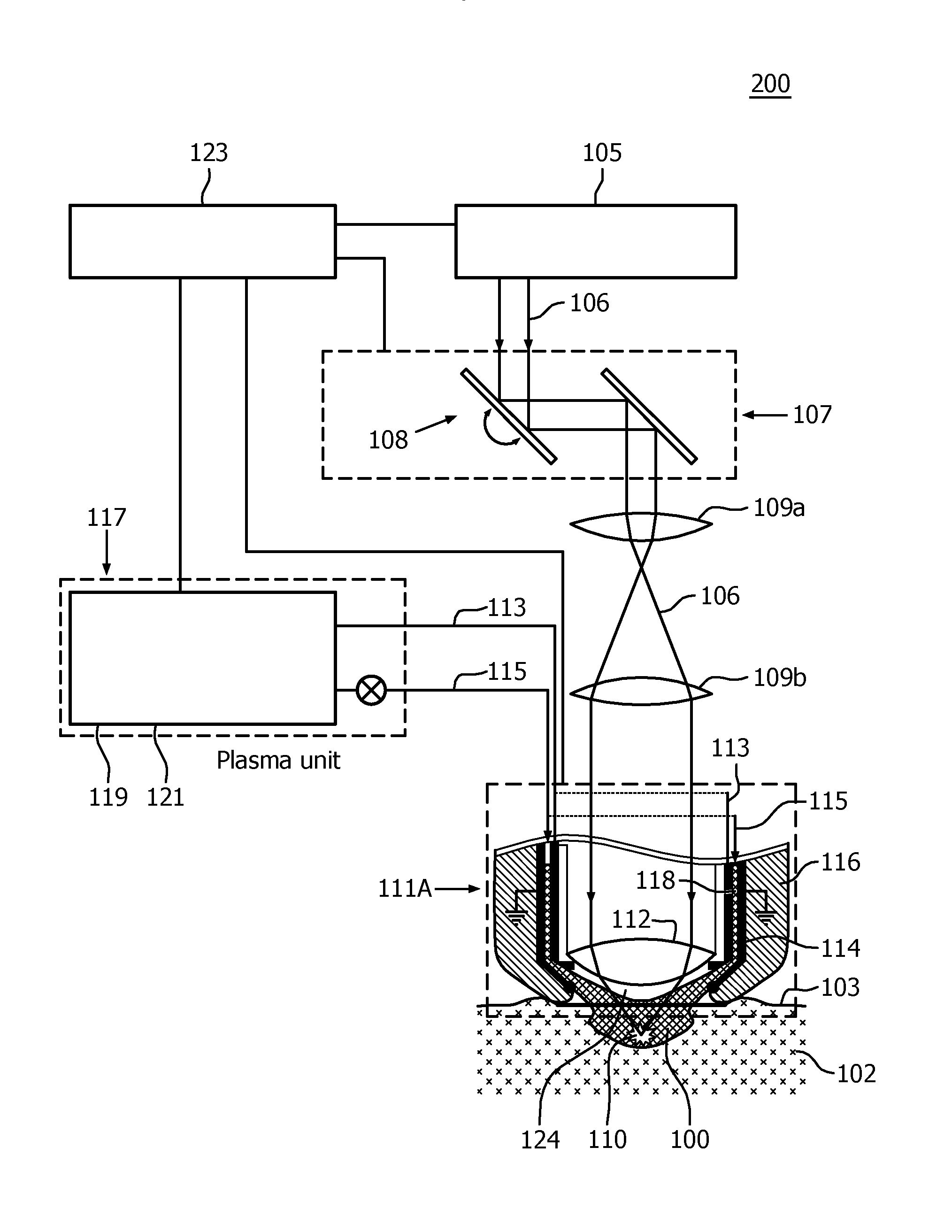
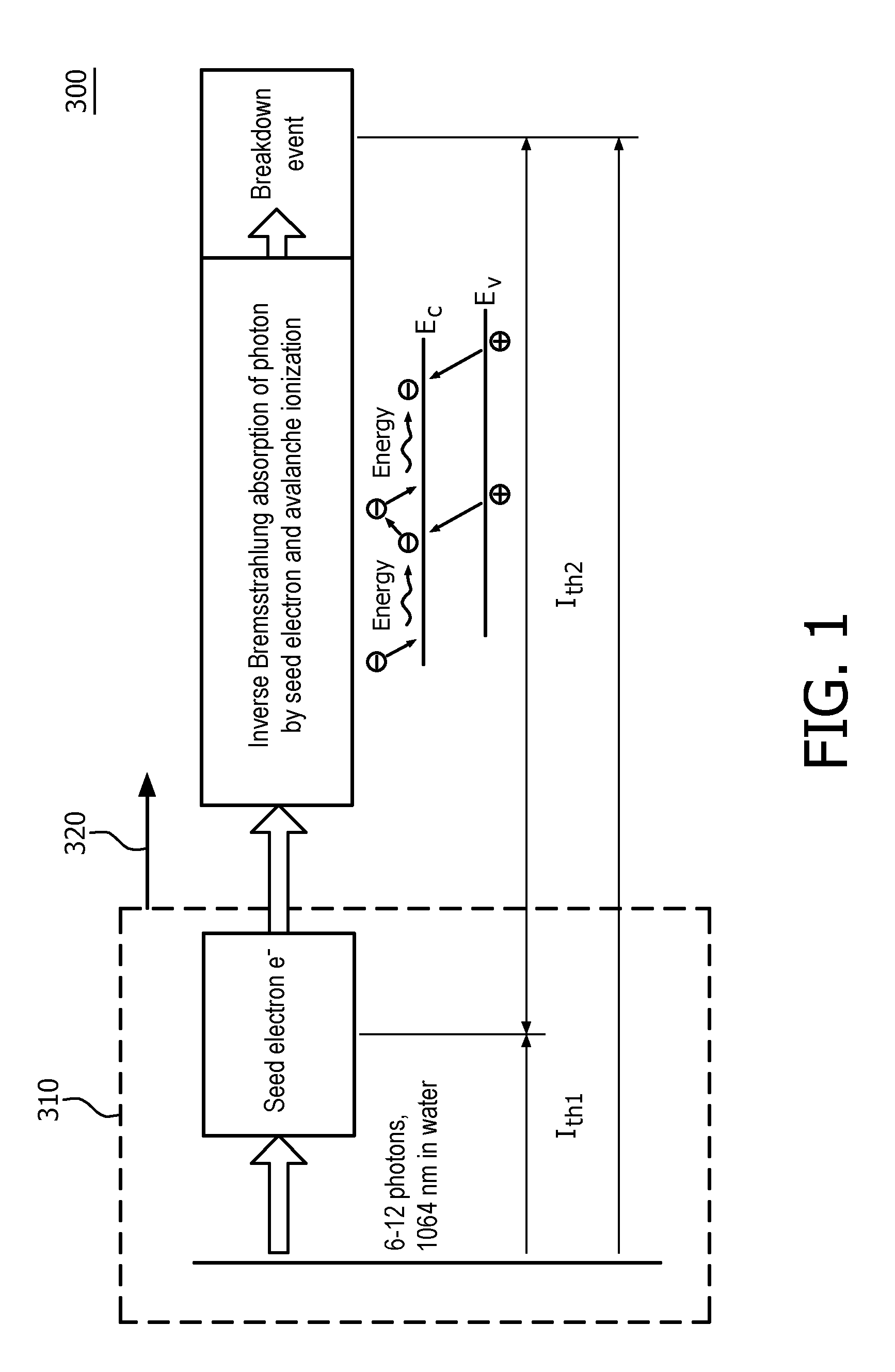
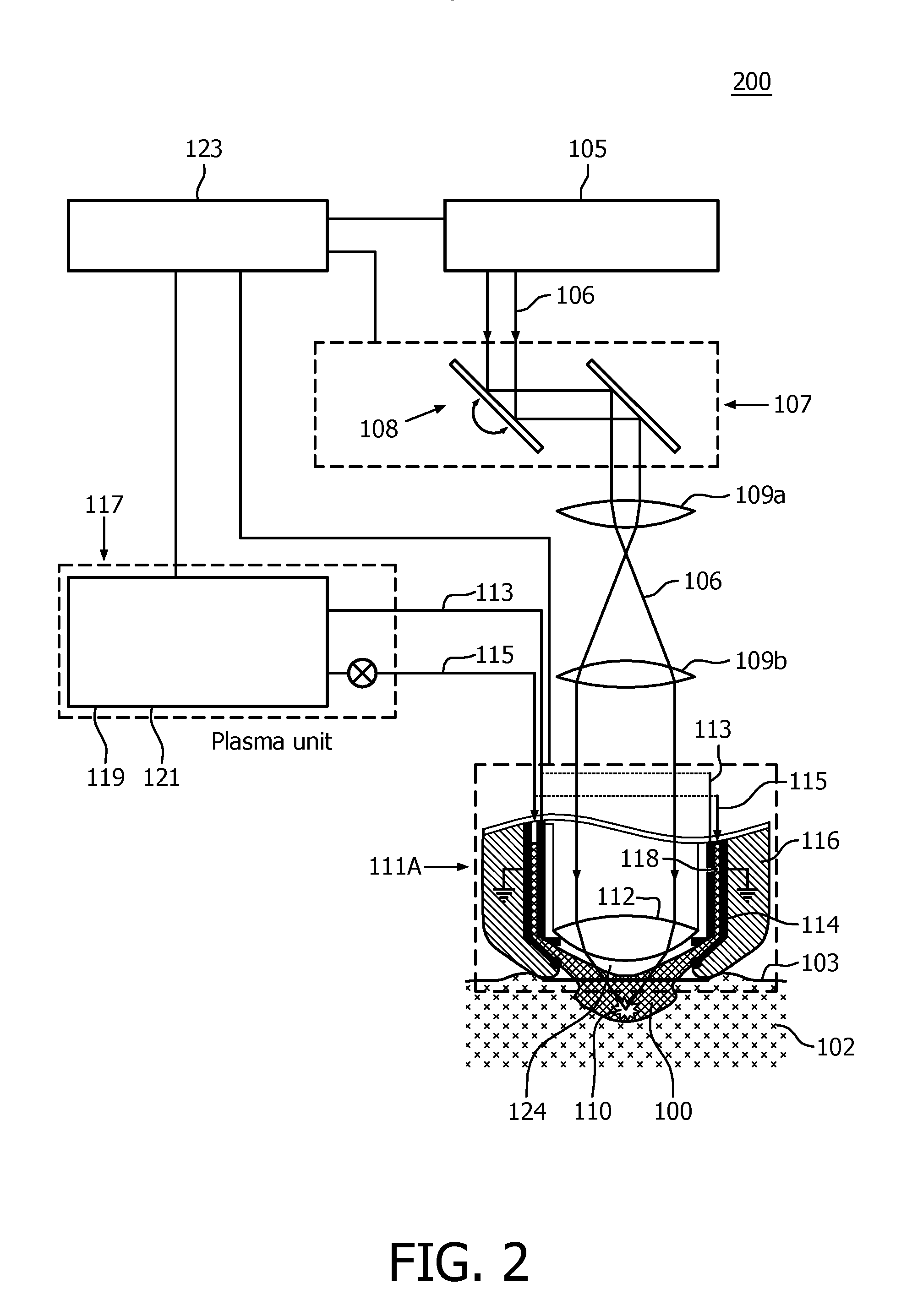
The invention is based on the idea that a laser beam with a high power density is required to generate a multiphoton ionization process in skin tissue. However, a plasma near the skin surface can generate a free electron that acts as a seed electron for the ionization process, reducing the required laser beam intensity. This reduces the risk of collateral damage to surrounding tissue and the overall power requirements of the treatment device. The plasma is generated by a plasma channel or a plasma jet directed towards the target position inside the skin tissue. The plasma channel may be a scanning system or multiple plasma units. The use of a plasma near the skin surface allows for a reduction in the treatment laser beam intensity required for the multiphoton ionization process.

Problems solved by technology

Achieving a multiphoton ionization process deep inside the skin is a challenging task.

Method used


Image

  • A skin treatment device for multiphoton ionization-based skin treatment
  • A skin treatment device for multiphoton ionization-based skin treatment
  • A skin treatment device for multiphoton ionization-based skin treatment

Examples


fourth embodiment

[0041]FIGS. 3A, 3B and 3C diagrammatically show a second, third and fourth embodiment of the skin treatment device 200 according to the invention. In FIGS. 3A, 3B and 3C, only the plasma-laser focusing units 111B, 111C, 111D, respectively, of the different embodiments are shown. All other elements such as the laser source 105, laser scanning unit 107, beam shaping system 109, plasma unit 117, and control unit 123 may be similar or identical to the embodiment shown in FIG. 2.

[0042]In contrast to the embodiment shown in FIG. 2, the plasma-laser focusing unit 111B shown in FIG. 3A comprises a dielectric barrier discharge system for generating the plasma 100. Dielectric-barrier discharges are characterized by the presence of one or more dielectric layers 104 in the discharge path extending from the anode 113 via the discharge space to the cathode 114. Different configurations of anode 113, cathode 114 and dielectric layers 104 are possible. For example, a planar configuration comprises ...

third embodiment

[0043]In the plasma-laser focusing unit 111C of the skin treatment device 200 as shown in FIG. 3B, the plasma-laser focusing unit 111C comprises a centered anode 113 at least partially surrounded by a tubular cathode 114 forming a plasma channel 118 positioned in the center of the plasma-laser focusing unit 111C. In the current embodiment, the laser beam shaping system 109 (not shown in FIG. 3B) generates an annular-shaped laser beam 106 which passes through the plasma-laser focusing unit 11C around the plasma channel 118. A single-focus lens system 112 is present for focusing the annular laser beam 106 into a target position 110 inside the skin tissue 102.

[0044]In the fourth embodiment of the plasma-laser focusing unit 111D of the skin treatment device 200 as shown in FIG. 3C, the plasma-laser focusing unit 111D again comprises the centered anode 113 at least partially surrounded by a tubular cathode 114 forming the plasma channel 118 positioned in the center of the plasma-laser fo...


PUM


Abstract

The invention provides a non-invasive skin treatment device (200) for generating a multiphoton ionization process at a target position (110) in skin tissue (102). The skin treatment device (200) comprises a laser source (105) configured and constructed for generating a laser beam (106), an optical system (109, 112) for focusing the laser beam into the target position below a skin surface (103), and a plasma unit (117) configured and constructed for generating a plasma (100) such that, in use, at least a portion of the plasma penetrates the skin tissue for generating at least one free electron at the target position. The skin treatment device further comprises a control unit (123) configured and constructed for controlling the laser source and the plasma unit such that, in use, at least a portion of the light of the laser beam is absorbed by said at least one free electron generated at the target position, thereby generating the multiphoton ionization process. A result of the use of the plasma in generating the multiphoton ionization process is that an overall laser beam intensity, required to generate the multiphoton ionization process, is reduced as compared to skin treatment devices which generate the multiphoton ionization process using a laser beam only.

Description

FIELD OF THE INVENTION[0001]The invention generally relates to the treatment of skin using laser light, and more particularly to a skin treatment device for generating a multiphoton ionization process in a target position in skin tissue.BACKGROUND OF THE INVENTION[0002]The desire to maintain a youthful appearance by preventing or reducing wrinkles in the skin is an important issue in human society. Many techniques have been designed to achieve the above issue. One of the techniques known from the published international patent application WO 2008 / 001284 A2 is to create a focal spot in a dermis layer of the skin to be treated. Said WO application discloses a skin treatment device with a laser source and focusing optics, wherein the power of the laser is selected such that Laser Induced Optical Breakdown (LIOB) affects the skin in order to stimulate re-growth of skin tissue and reduce wrinkles. This LIOB is based on strong non-linear absorption of the laser light by the skin tissue, w...

Claims


Application Information

Patent Timeline
Patent Type & Authority Applications(United States)
IPC IPC(8): A61N5/06A61B18/20A61N1/44A61B18/04
CPCA61N5/0616A61B18/042A61B18/203A61N2005/0626A61B2018/00994A61B2018/0047A61N2005/067A61N1/44A61B2018/00452A61B2018/00583A61B18/20A61N5/067
Inventor VARGHESE, BABUVERHAGEN, RIEKOJURNA, MARTINPALERO, JONATHAN ALAMBRAHORTON, MARGARET RUTHBONITO, VALENTIA
Owner KONINKLJIJKE PHILIPS NV
Learn More