
Composition for electrode of capacitive deionization apparatus and electrode including same

Inactive Publication Date: 2016-09-22
SAMSUNG ELECTRONICS CO LTD
View PDF6 Cites 10 Cited by
  • Summary
  • Abstract
  • Description
  • Claims
  • Application Information

AI Technical Summary

Benefits of technology

The electrode composition in this patent improves the production of a capacitive deionization apparatus by allowing the active material of the electrode to cure quickly and preventing the surface of the electrode from having cracks.

Problems solved by technology

Water having a high mineral content (i.e., hard water) may cause problems of easy occurrence of lime scales in the interior walls of pipes and a sharp decrease in energy efficiency when it is used for home installations, for example, in a heat exchanger or a boiler.
In addition, hard water is inappropriate for use as wash water.
Further, demands for seawater desalination have increased as larger areas are suffering from water shortages.

Method used


Image

  • Composition for electrode of capacitive deionization apparatus and electrode including same
  • Composition for electrode of capacitive deionization apparatus and electrode including same
  • Composition for electrode of capacitive deionization apparatus and electrode including same

Examples


preparation example 1

Manufacture of Cathode for Capacitive Deionization Apparatus (CDI)

[0108]A cathode as a counter electrode for the anodes according to Examples 6 to 13 is manufactured in the following method.

[0109](1) First, in order to prepare a binder, 2.1 g of glycidyl trimethylammonium chloride (GTMAC) is added to 12.6 g of a PVA 10% aqueous solution, and the mixture is agitated.

[0110](2) 0.45 g of Super-P as a conductive agent and 3 g of activated carbon are added to the prepared polymer solution, and the mixture is agitated with a Thinky mixer for 10 minutes.

[0111](3) 0.72 g of glutaric acid as a cross-linking agent is injected into the prepared slurry, and the mixture is agitated with a Thinky mixer for 10 minutes.

[0112](4) The prepared slurry is coated to be 200 μm to 300 μm thick on one side of a conductive graphite sheet (thickness=250 μm) with a doctor blade.

[0113](5) The coated sheet is dried at room temperature for 3 hours and heat-treated at 130° C. for 2 hours.

[0114](6) The heat-treate...

preparation example 2

Assembly of Capacitive Deionization Apparatus (CDI)

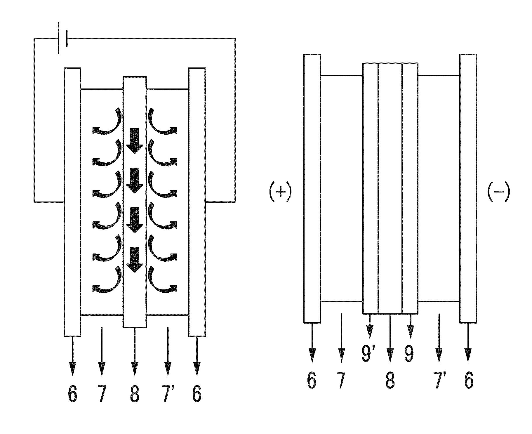
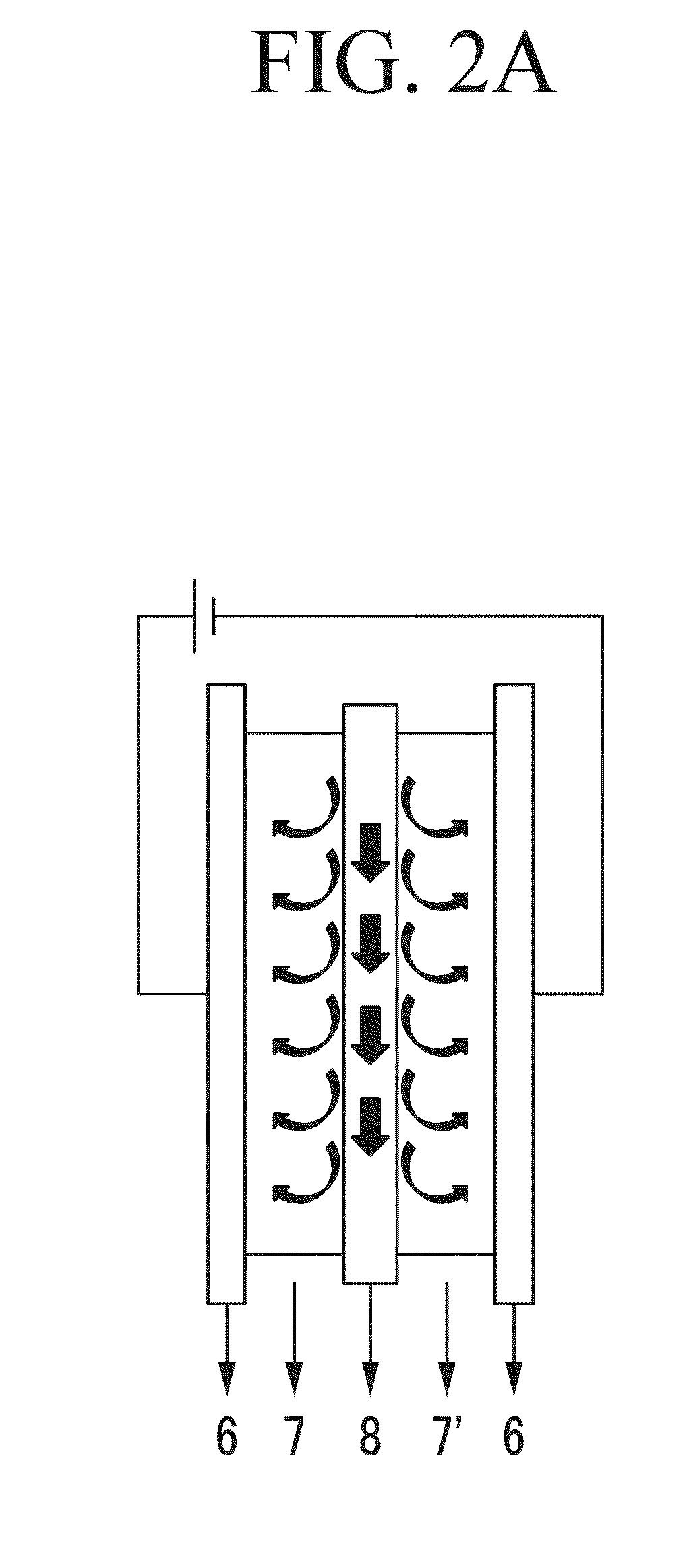
[0115]The anodes according to Examples 6 to 13 and the cathode according to Preparation Example 1 are used with a water-permeating open polyamide mesh as a spacer to manufacture a capacitive deionization (CDI) apparatus. The CDI apparatus is manufactured by sequentially laminating “graphite plate / anode / spacer / cathode / graphite plate” and fastening them together with screws.

experimental example 1

Evaluation of Ion Removal Performance of Capacitive Deionization (CDI) Apparatus

[0116]Ion adsorption removal experiments of the CDI apparatuses are performed according to the following procedure, and the results are respectively provided in Tables 3 to 7 and FIGS. 3 to 5.

[0117](1) The CDI apparatus is operated at room temperature by providing 250 mg / L of a standard hard water solution (conductivity: −830 ρS / cm) at a rate of 27-28 mL / min.

[0118](2) Each electrode is connected to electric power to maintain a cell voltage (a potential difference between anode and cathode) at 1.5 V for one minute for deionization, and then at −0.8 V for reproduction.

[0119](3) Conductivity of water passed through the apparatus is measured in real time by using a flow-type conductivity sensor.

[0120](4) The amount of electric charge in each step is measured from the amount of a current supplied through a power source.

[0121](5) The measured ion conductivity is used to calculate an ion removal rate (%) of the...


PUM

PropertyMeasurementUnit
Percent by massaaaaaaaaaa

Abstract

A binder composition for an electrode of a capacitive deionization apparatus includes a hydrophilic polymer, a cross-linking agent, an ion exchange group, and a latex in a form of an emulsion polymer having an ionic functional group on the surface.

Description

CROSS REFERENCE TO RELATED APPLICATIONS[0001]This is a National Phase Application of PCT / KR2014 / 011202, filed Nov. 20, 2014, which is an International Application claiming priority to Korean Application No. 10-2013-0141511, filed Nov. 20, 2013, the entire contents of each of which are herein incorporated by reference.TECHNICAL FIELD[0002]Example embodiments are directed to an electrode composition for a capacitive deionization apparatus and an electrode for a capacitive deionization apparatus including the same.BACKGROUND ART[0003]In some regions, domestic water may include a large amount of minerals. In Europe and other regions, limestone substances frequently flow in underground water, and thus tap water in these regions contains a large amount of minerals. Water having a high mineral content (i.e., hard water) may cause problems of easy occurrence of lime scales in the interior walls of pipes and a sharp decrease in energy efficiency when it is used for home installations, for ex...

Claims


Application Information

Patent Timeline
IPC IPC(8): C02F1/469C08L29/04C02F1/46
CPCC02F1/4691C02F1/4604C02F1/4602C08L29/04C02F2101/10C02F2103/08C08L2312/00C02F2307/12C02F2303/22C02F2201/48C08L2201/52C08L2203/20C02F2103/04C25B11/04B01J39/18B01J41/12C02F2201/4616
Inventor CHOI, YEONG SUKLEE, SEUNG JAEJEONG, JOON SEON
Owner SAMSUNG ELECTRONICS CO LTD
Learn More