Method and device for pyrolysis of biomass to produce syngas

a biomass and pyrolysis technology, applied in the field of biomass gasification, can solve the problems of low efficiency of energy transfer from biomass to syngas, and achieve the effects of high carbon conversion efficiency, strong processing capacity and good quality of syngas

Inactive Publication Date: 2016-09-22
WUHAN KAIDI ENG TECH RES INST CO LTD
View PDF0 Cites 6 Cited by
  • Summary
  • Abstract
  • Description
  • Claims
  • Application Information

AI Technical Summary

Benefits of technology

[0030]1. The microwave and the plasma are coupled for pyrolysis of the biomass. The heating process has no thermal inertia. The pyrolysis is performed in the high-temperature ionic state. The pyrolysis is complete and the combustible compositions are converted into syngas completely. The carbon conversion efficiency is high. The quality of the syngas is good. The volume content of the effective gas exceeds 90%.
[0031]2. The biomass is fed to the pyrolysis furnace under pressures. The single furnace has strong processing capacity. No compressor is required in the subsequent utilization process so a lot of compression work and energy consumption are saved.
[0032]3. The syngas contains no tar. The subsequent purifying technique is simple and causes no pollution.
[0033]4. The biomass is fed in a dense-phase static pressure mode. The biomass does not need to be crushed excessively. The device and the method are economical.

Problems solved by technology

Conventionally, the pyrolysis and gasification of biomass has the following disadvantages: 1. The efficiency of energy transfer from biomass to syngas is low.

Method used


Image

  • Method and device for pyrolysis of biomass to produce syngas
  • Method and device for pyrolysis of biomass to produce syngas

Examples


Embodiment Construction

[0036]For further illustrating the invention, experiments detailing a device and method for pressurized pyrolysis of biomass with rice hulls as an example are described below. It should be noted that the following examples are intended to describe and not to limit the invention.

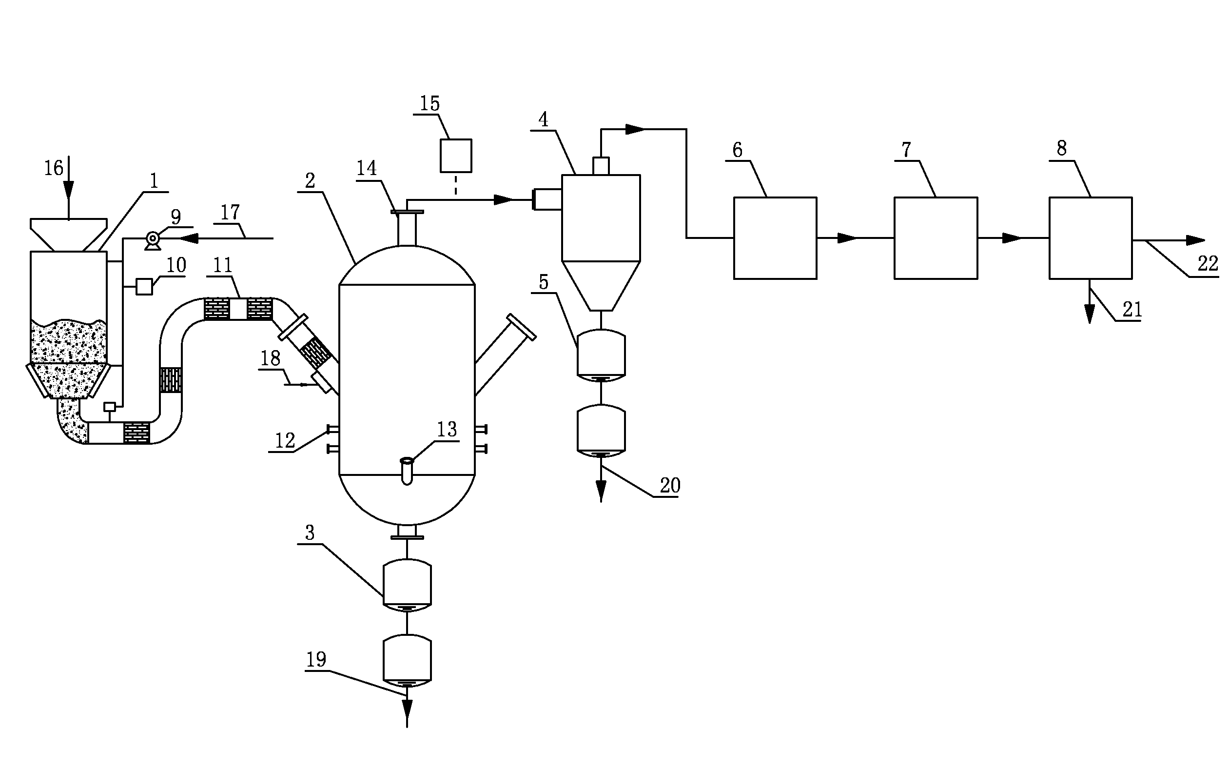
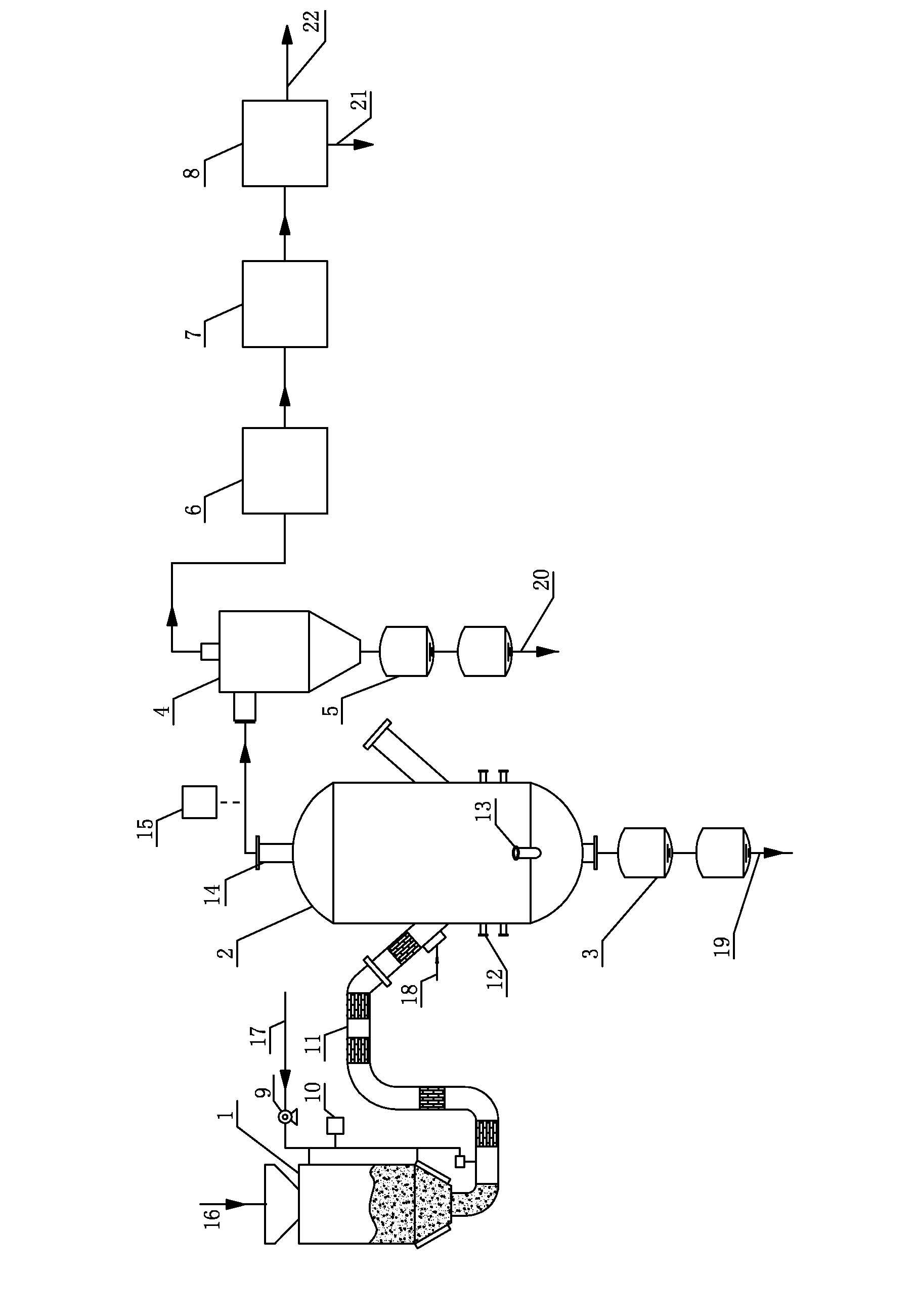
[0037]A device for pressurized pyrolysis of biomass as shown in the sole figure comprises a pyrolysis furnace 2, a pulse-type feeding system 1 and a cyclone separator 4. The pyrolysis furnace 2 is a cylinder in shape; the outer wall of the pyrolysis furnace is made of steel; and the inner wall of the pyrolysis furnace is built by refractory bricks or has a water wall. The high-temperature syngas outlet 14 is arranged at the top of the pyrolysis furnace 2; the feeding ports are arranged on both sides of the middle part of the pyrolysis furnace; a plurality of microwave inlets 12 and interfaces of plasma torch 13 are arranged in the lower part of the pyrolysis furnace; and the slag outlet is arranged at the bot...


PUM

PropertyMeasurementUnit
temperatureaaaaaaaaaa

Abstract

A method for pressurized pyrolysis of biomass in a pressurized pyrolysis furnace, including: 1) crushing and screening biomass; collecting biomass having desired particle sizes; and delivering the biomass having desired particle sizes to a pulse-type feeding system; 2) transporting the biomass to a pyrolysis furnace via the pulse-type feeding system; synchronously initiating microwave and a plasma torch, the microwave producing a microwave field in the pyrolysis furnace, working gas of the plasma torch being ionized for the first time to produce plasma jet entering the pyrolysis furnace; and 3) allowing the syngas generated in 2) to continue moving upwards and introducing the syngas out from the top of the pyrolysis furnace; chilling the syngas; introducing the syngas to a cyclone separator to separate residues; and then cooling and purifying the syngas using a cooling device and a purifying device, respectively, to produce clean syngas.

Description

CROSS-REFERENCE TO RELATED APPLICATIONS[0001]This application is a continuation-in-part of International Patent Application No. PCT / CN2014 / 090887 with an international filing date of Nov. 12, 2014, designating the United States, now pending, and further claims priority benefits to Chinese Patent Application No. 201310628406.X filed Nov. 29, 2013. The contents of all of the aforementioned applications, including any intervening amendments thereto, are incorporated herein by reference. Inquiries from the public to applicants or assignees concerning this document or the related applications should be directed to: Matthias Scholl P.C., Attn.: Dr. Matthias Scholl Esq., 245 First Street, 18th Floor, Cambridge, Mass. 02142.BACKGROUND OF THE INVENTION[0002]1. Field of the Invention[0003]The invention relates to the gasification of the biomass, and more particularly to a method and device for pyrolysis of biomass to produce syngas using microwaves and plasma.[0004]2. Description of the Relat...

Claims


Application Information

Patent Timeline
Patent Type & Authority Applications(United States)
IPC IPC(8): C10J3/46C10J3/48C10K1/02C10J3/84
CPCC10J3/466C10J3/84C10J3/485C10K1/026C10J2200/15C10J2300/0973C10J2300/0916C10J2300/0969C10J2300/0959C10J2300/1238C10J2300/0906C10B53/02C10J3/18C10B19/00C10J2300/123Y02P20/145Y02E50/10Y02P20/10C10B23/00
Inventor ZHANG, YANFENGZHANG, LIANGCHEN, YILONG
Owner WUHAN KAIDI ENG TECH RES INST CO LTD
Why Eureka
Try Eureka