A time variant antenna for transmitting wideband signals

a wideband signal and time variant technology, applied in the direction of simultaneous aerial operations, antennas, frequency-modulated carrier systems, etc., can solve the problems of high-bandwidth data transmission, strict follow-up of the fundamental physical limit of the antenna, and significant problems

Active Publication Date: 2016-10-06
VIRGINIA TECH INTPROP INC
View PDF2 Cites 11 Cited by
  • Summary
  • Abstract
  • Description
  • Claims
  • Application Information

AI Technical Summary

Problems solved by technology

Although there have been studies on different techniques to broaden the bandwidth of small antennas, the antenna bandwidth strictly follows the fundamental physical limit.
This problem becomes significant when a high-rate data-transmission is required along with a very small-size antenna.
Even though a high data-rate can be achieved in broadband systems by increasing the carrier frequency, in low-frequency applications such as biomedical implantable devices, high-bandwidth data-transmission remains an open challenge.

Method used


Image

  • A time variant antenna for transmitting wideband signals
  • A time variant antenna for transmitting wideband signals
  • A time variant antenna for transmitting wideband signals

Examples


example 1

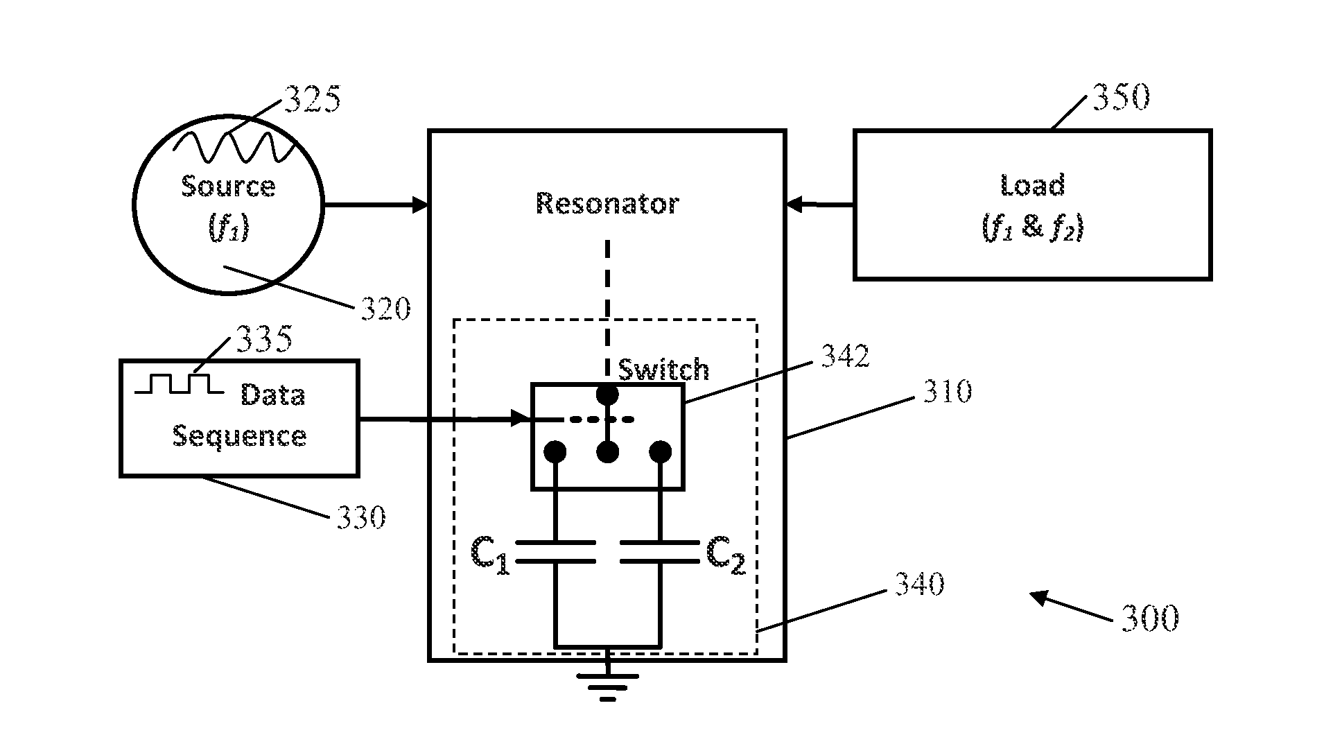
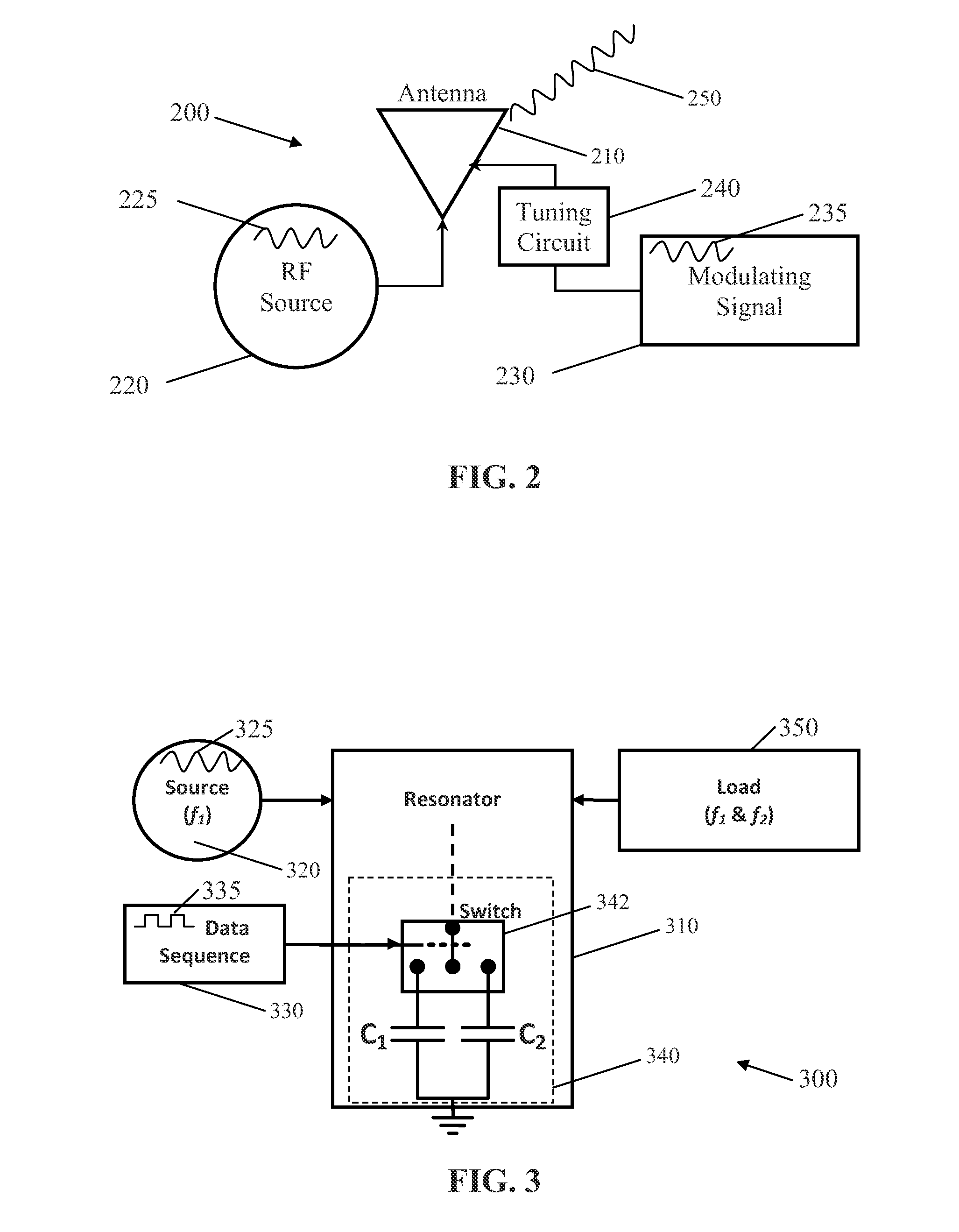
[0120]A simulation of the circuit 400 was implemented using Agilent Advance Design System. Component values are chosen to have a high Q resonator with two resonant frequencies f1=500 MHz and f2=300 MHz with Q1=119 and Q2=198 before and after the switching of the capacitor, C2, respectively. A single-pole single-throw voltage-controlled switch was used for the switch 442 to switch the capacitor, C2. A step function signal u(t−ts) was employed to trigger the switch 442 at ts.

[0121]The source signal 425 was programmed to be a sinusoidal voltage signal at 500 MHz with an amplitude of 2 V. FIG. 9A shows the voltage at the load. RL, at ts=400 ns and ts=400.5 ns, which correspond to the zero and maximum crossing of the voltage, respectively. As is depicted in FIG. 9A, right after the switching instant the voltage waveform at the load, RL, shifts to the new resonant frequency, 300 MHz. Also, the magnitude of first peaks for each case agrees with predicted value in Equations 21 and 34.

[0122]...

example 2

[0125]FIGS. 9D and 9E illustrate simulations of FSK signals generated by different switching frequencies of the switch 442, respectively fswitch=50 MHz and fswitch=20 MHz. Since each switching pulse represents a pair of 0 and 1, data rate is twice that of the switching frequency. In fact, by using a fast switching mechanism, a simple narrowband RLC resonator, e.g., that of the circuit 400, excited by a single-tone source. e.g., the source 420, can be employed to generate high data rate FSK signals. The mark frequency is same as the source frequency and the space frequency can be tuned by the switched capacitor, C2. Moreover, by using a variable capacitor, such as a varactor diode, for the capacitor, C1+C2, one can easily tune the space frequency as required.

[0126]A mockup of the circuit 400 has been tested. A PIN diode with 9 ns nominal reverse recovery time was used to create a shunt RF switch for the switch 442. The resonator 410+capacitor, C2, +load, RL, was made of surface mount...

example 3

[0128]Since a high-Q antenna can be characterized by a high-Q resonator, the entire analysis of a switched resonator can be applied to a high-Q antenna. The configuration for a modulated antenna is presented in FIG. 5, and an exemplary embodiment of the antenna 510 is illustrated in FIG. 11A. In an exemplary embodiment, the PIFA antenna 1000 illustrated in FIG. 11A can be miniaturized for use in implanted devices.

[0129]A simulation of the circuit 500 in which the antenna 510 is embodied as the antenna was run. The antenna 1000 was loaded with two switched capacitors, C1 and C2, generating two resonant frequencies, namely 400 MHz and 500 MHz. FIG. 13A shows the voltage at the tuning port 1030, and FIG. 13B shows the pulse train 535.

[0130]Similar to the resonator 410, 410′, the switching time, ts, of the capacitors, C1 and C2, should by synchronous with the zero crossing of the capacitor, C1 or C2, voltage in order to transmit at maximum power. FIGS. 14A and 14B show the radiated fiel...


PUM


Abstract

A circuit for tuning a resonance frequency of an electrically small antenna. The circuit includes a first source configured for providing a modulation signal, a second source configured for providing a periodic electrical signal, an antenna, and a tuning circuit configured for modulating a resonance frequency of the antenna in response to the modulation signal. The tuning circuit includes first and second capacitors that are alternately coupled to the antenna to change the resonance frequency of the antenna. The capacitor currently coupled to the antenna is decoupled from the antenna and the other capacitor is coupled to the antenna when the voltage across the capacitor currently coupled to the antenna is momentarily zero. In an exemplary embodiment, the tuning circuit comprises first and second inductors rather than capacitors. The inductors are switched into and out of the circuit when the current through the currently coupled inductor is momentarily zero.

Description

CROSS REFERENCE TO RELATED APPLICATION[0001]This application claims the benefit of U.S. Provisional Application No. 61 / 906,652, entitled “A Wideband Frequency-Shift Keying Modulation Technique Using Transient State of a Small Antenna” and filed Nov. 20, 2013, the contents of which application are incorporated herein by reference.FIELD OF THE INVENTION[0002]The present invention relates to a time variant antenna for transmitting wideband signals and more specifically to a circuit including a high-Q, time variant antenna for transmitting wideband signals and a tuning circuit for changing the resonant frequency of the antenna.BACKGROUND OF THE INVENTION[0003]Wireless communication techniques have been widely developed during the past decades due to their extensive applications. One desirable characteristic of most wireless systems is a wide bandwidth. Although there have been studies on different techniques to broaden the bandwidth of small antennas, the antenna bandwidth strictly foll...

Claims


Application Information

Patent Timeline
Patent Type & Authority Applications(United States)
IPC IPC(8): H01Q3/34H01Q5/25H01Q9/04
CPCH01Q3/34H01Q5/25H01Q9/0421H04B1/04H01Q3/44H01Q5/00H04B1/006H04L27/12
Inventor MANTEGHI, MAJIDSALEHI, MOHSEN
Owner VIRGINIA TECH INTPROP INC
Why Eureka
Try Eureka