Injected metal bead channel seal achieved through stamped plate features on fuel cell bipolar plates

a fuel cell bipolar plate and stamped plate technology, applied in the direction of cell components, final product manufacturing, sustainable manufacturing/processing, etc., can solve the problems of long manufacturing cycle time, high cost, and high cost of above sealing approaches to achieve high volume bipolar plate production, and achieve the effect of sealing

Active Publication Date: 2016-10-13
GM GLOBAL TECH OPERATIONS LLC
View PDF2 Cites 6 Cited by
  • Summary
  • Abstract
  • Description
  • Claims
  • Application Information

AI Technical Summary

Benefits of technology

[0007]It is an object of the disclosure to utilize stamped features and a sealant injection device to form coolant channel plugs within an MBS-based bipolar plate seal design. According to one aspect of the present invention, a fuel cell system includes a fuel cell stack made up of numerous cells each of which includes an MEA cooperative with a bipolar plate assembly. The bipolar plate assembly includes one or more plates each of which define a fluid-engaging surface where one or more of reactant channels and coolant channels are formed. Similarly, inlet and outlet flowpaths are formed in the fluid-

Problems solved by technology

The CIP approach is costly and often requires long manufacturing cycle times to properly cure the seal materials, while both are only suitable for low volume applications, where high manufacturing and material costs could be tolerated.
Unfortunately, commercial automotive fuel cell applications require high volume manufacturing solutions that can produce 10,000 to 100,000 fuel cell stacks per year (each with roughly 300 to 400 cells per stack).
The above sealing approaches would be a cost-prohibitive way to achieve high volume bipolar plate production.
While such a configuration is more compatible with the high-volume production needs mentioned above, the metal-to-metal connection makes it difficult to ensure that additional leakage paths aren't introduced where coolant or other fluids can fill the channels fo

Method used


Image

  • Injected metal bead channel seal achieved through stamped plate features on fuel cell bipolar plates
  • Injected metal bead channel seal achieved through stamped plate features on fuel cell bipolar plates
  • Injected metal bead channel seal achieved through stamped plate features on fuel cell bipolar plates

Examples


Embodiment Construction

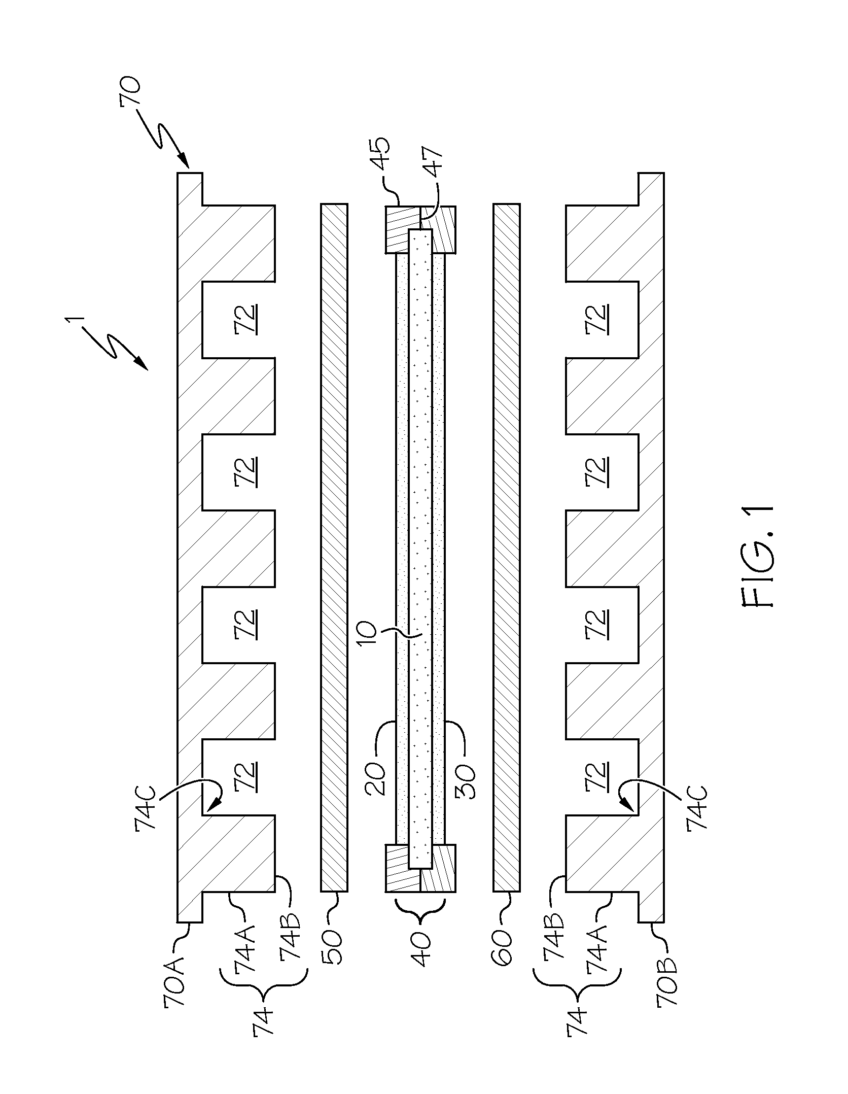
[0017]Referring initially to FIG. 1, a simplified view of a PEM fuel cell 1 in exploded form is shown. The fuel cell 1 includes a substantially planar proton exchange membrane 10, anode catalyst layer 20 in facing contact with one face of the proton exchange membrane 10, and cathode catalyst layer 30 in facing contact with the other face. Collectively, the proton exchange membrane 10 and catalyst layers 20 and 30 are referred to as the MEA 40. An anode diffusion layer 50 is arranged in facing contact with the anode catalyst layer 20, while a cathode diffusion layer 60 is arranged in facing contact with the cathode catalyst layer 30. Each of diffusion layers 50 and 60 are made with a generally porous construction to facilitate the passage of gaseous reactants to the catalyst layers 20 and 30. Collectively, anode catalyst layer 20 and cathode catalyst layer 30 are referred to as electrodes, and can be formed as separate distinct layers as shown, or in the alternate (as mentioned above...


PUM


Abstract

A fuel cell system with reduced leakage and a method of assembling a fuel cell system. Bipolar plates within the system include reactant channels and coolant channels that are fluidly coupled to inlet and outlet flowpaths, all of which are formed within a coolant-engaging or reactant-engaging surface of the plate. One or more seals are also formed on the fluid-engaging surface to help reduce leakage by maintaining fluid isolation of the reactants and coolant as they flow through their respective channels and flowpaths that are defined between adjacently-placed plates. The seal—with its combination of in-plane and out-of-plane dimensions—forms a substantially hollow volume, into which a plug is placed to reduce the tendency of the seal to form a shunted flow of the coolant or reactant around the intended active area of the plate. A fluid port intersection is integrally formed with the seal and is formed to be fluidly cooperative with the volume, and is capable of accepting the introduction of a fluent precursor of the plug material such that upon curing, the precursor material forms a substantially rigid insert that continuously fills both the volume and intersection, thereby increasing the resistance of the plug to movement and the seal to shunted flow. In one form, the geometry of the fluent material injection site is such that it promotes plug anchoring within its intended location, while also providing a manufacturing aid to visually inspect for plug installation, as well as to serve as a bipolar plate stacking alignment locator and verification.

Description

BACKGROUND OF THE INVENTION[0001]The present invention relates generally to an apparatus and method for improved sealing within bipolar plates used in a fuel cell assembly, and more particularly to the use of a seal formed within the plate where a volume within the seal houses a plug to avoid shunted fluid flow that would otherwise traverse a bead path formed by the seal.[0002]Fuel cells convert a fuel into usable electricity via electrochemical reaction. A significant benefit to such an energy-producing means is that it is achieved without reliance upon combustion as an intermediate step. As such, fuel cells have several environmental advantages over internal combustion engines (ICEs) for propulsion and related motive applications. In a typical fuel cell—such as a proton exchange membrane or polymer electrolyte membrane (in either event, PEM) fuel cell—a pair of catalyzed electrodes are separated by an ion-transmissive medium (such as Nafion™) in what is commonly referred to as a m...

Claims


Application Information

Patent Timeline
IPC IPC(8): H01M8/02H01M8/24
CPCH01M8/0258H01M8/2485H01M2008/1095H01M8/0276H01M2250/20H01M8/0297H01M4/8631H01M8/04074H01M8/0206H01M8/0271H01M8/028H01M8/0286Y02P70/50Y02T90/40Y02E60/50
Inventor FREESE, V, CHARLES E.
Owner GM GLOBAL TECH OPERATIONS LLC
Why Eureka
Try Eureka