Method And Equipment Based On Detecting The Polarization Property Of A Polarization Maintaining Fiber Probe For Measuring Structures Of A Micro Part

a technology of polarization maintaining fiber and micro-parts, which is applied in the direction of mechanical measuring arrangements, instruments, optical apparatus testing, etc., can solve the problems of difficult to further enhance the inspection resolution of fiber probes, present challenges to the measurement precision and inspection depth of existing probing systems, and complex fabrication processes of their probes

Active Publication Date: 2016-10-20
HARBIN INST OF TECH
View PDF2 Cites 12 Cited by
  • Summary
  • Abstract
  • Description
  • Claims
  • Application Information

AI Technical Summary

Benefits of technology

[0011]4. The inspecting resolutions of fiber probes are hard to be further enhanced. Most of fiber probes hav

Problems solved by technology

With fast development of manufacturing technologies, more and more structures of micro parts with dimensions of 0.1˜1 mm and aspect ratios of more than 10:1 are now used in an increasing number of applications, including ink-jet printer nozzles, microgroove arrays in aerospace propulsion engines, cooling vents in turbine blades, diesel fuel injection holes and devices of binary optics, which present challenges to the measurement precision and inspecting depth of existing probing systems.
However, the fabrication process of their probe is complex and the production cost is high.
But due to shadowing effect, a CCD camera cannot obtain enough light energy to create an image, and the inspecting depth achievable with this probe is thus limited.
This probe extends the range of inspecting depth, but how to realize three-dimensional measurement and fabricate a smaller fiber coupler with a high coupling efficiency is still an open issue.
However, limitations of this approach include that the

Method used


Image

  • Method And Equipment Based On Detecting The Polarization Property Of A Polarization Maintaining Fiber Probe For Measuring Structures Of A Micro Part
  • Method And Equipment Based On Detecting The Polarization Property Of A Polarization Maintaining Fiber Probe For Measuring Structures Of A Micro Part
  • Method And Equipment Based On Detecting The Polarization Property Of A Polarization Maintaining Fiber Probe For Measuring Structures Of A Micro Part

Examples


Embodiment Construction

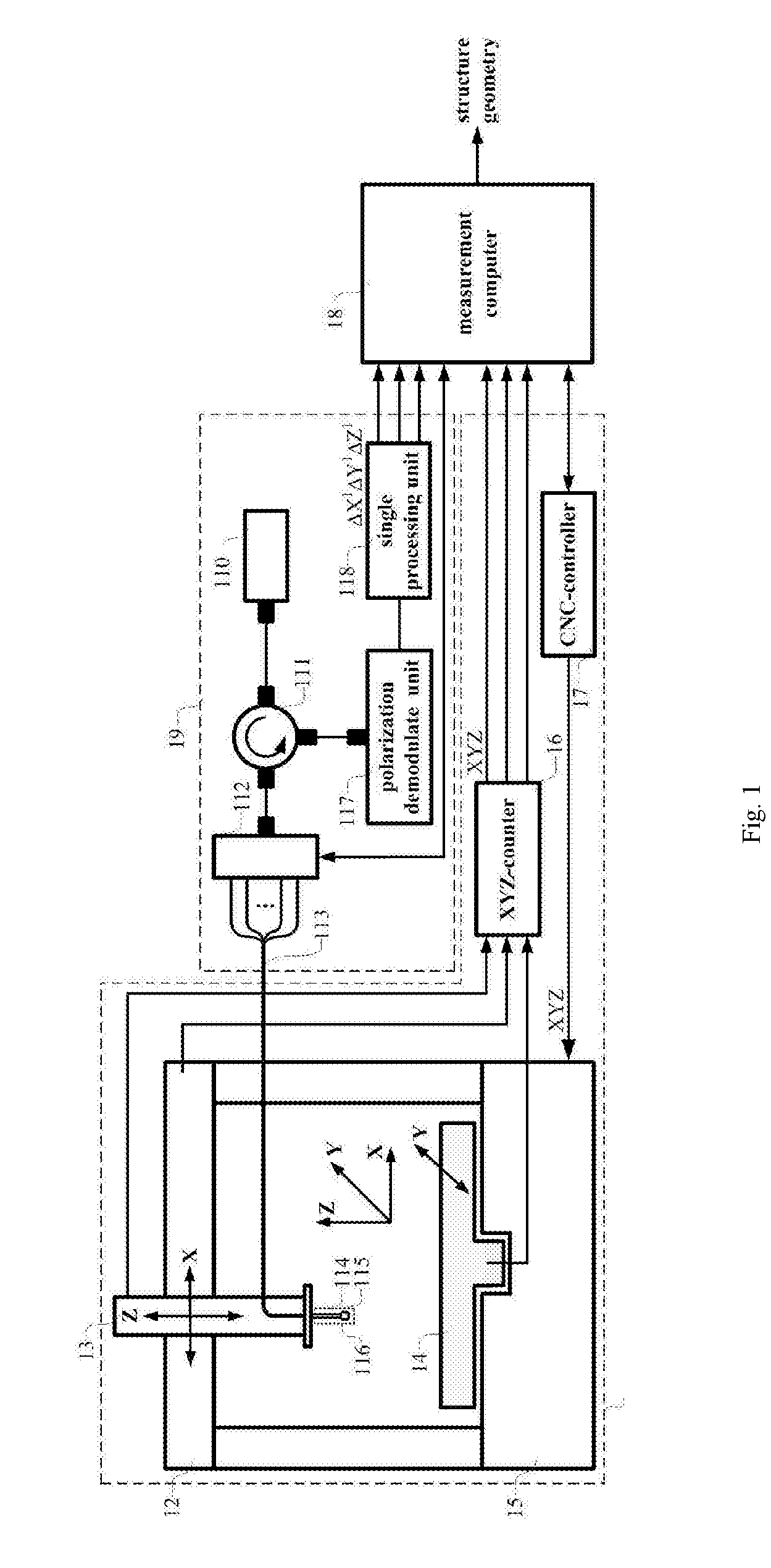
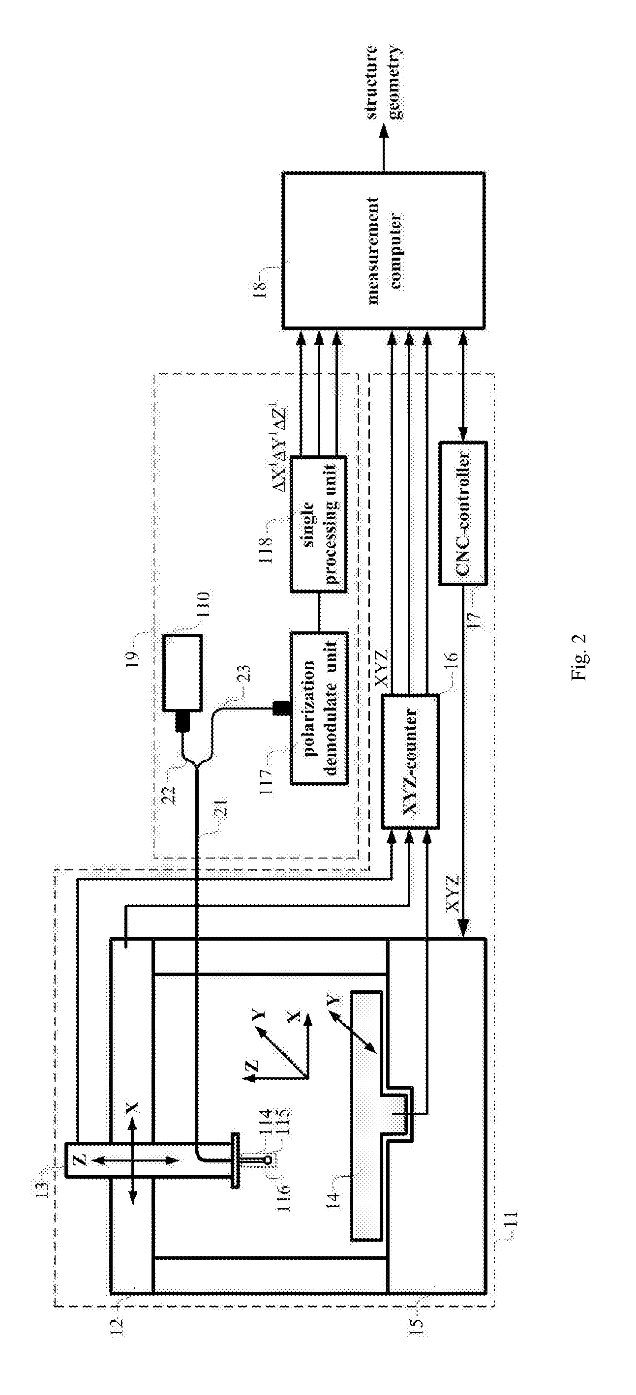
[0060]A method based on detecting the polarization property of a PMF probe for measuring structures of a micro part, which consists of following steps:

[0061]Step 1. Providing a PMF probe, which comprises a spherical tip and a PMF stylus. The PMF stylus is cantilevered at one end and with the spherical tip fixed on the other end. The PMF stylus of the PMF probe contains one or more PMFs;

[0062]In step 1, the PMF stylus which consists of one or more PMFs with a spherical tip in the end is served as a PMF probe. The incident light of the PMF probe is linearly polarized light. When the spherical tip of the PMF probe is subjected to a radial contact displacement, the PMF stylus suffers a corresponding stress caused by the radial contact displacement of the spherical tip. This stress induces refractive index changes of the fast axis and slow axis of PMFs of the PMF stylus, and this means changes of transmission constants of two orthogonal polarization modes propagating in PMFs of the PMF s...


PUM


Abstract

A method and equipment based on detecting the polarization property of a polarization maintaining fiber (PMF) probe for measuring structures of a micro part are provided. The provided method relates to how to accomplish measuring structures of a micro part by transforming two or three-dimensional contact displacements into polarization property changes of the PMF probe, and how to reconstruct the structure geometry of a micro part. The provided equipment can be used to bring the spherical tip of the PMF probe into contact with a micro part, to determine coordinates of contact points, and to reconstruct the structure geometry of a micro part. The provided method and equipment feature high sensitivity, low probing force, high inspecting aspect ratio and immunity to environment interference.

Description

FIELD OF INVENTION[0001]The invention relates to a method based on detecting the polarization property of a PMF probe for measuring structures of a micro part, wherein structure measurement of a micro part is accomplished by transforming two or three-dimensional contact displacements into polarization property changes of the PMF probe and the structure geometry of a micro part is reconstructed. The invention also relates to an equipment based on detecting the polarization property of a PMF probe for measuring structures of a micro part, and the equipment consists of a coordinate measuring instrument system, a probing system and a measurement computer, wherein the spherical tip of the PMF probe is brought into contact with a micro part, and contact points of a micro part can be calculated from coordinates of the PMF probe relative to the coordinate measuring instrument system and contact displacements of the spherical tip of the PMF probe relative to its zero-force position measured ...

Claims


Application Information

Patent Timeline
IPC IPC(8): G01B11/00G01B5/012
CPCG01B5/012G01B11/007G01B11/18G01B11/005G01M11/00G01M11/08G01M11/30G01M11/31G01M11/3181
Inventor CUI, JIWENLI, JUNYINGFENG, KUNPENGTAN, JIUBIN
Owner HARBIN INST OF TECH
Why Eureka
Try Eureka