
Multi-scale mesh modeling software products and controllers

a multi-scale mesh and simulation software technology, applied in the field of modeling and simulation software products, can solve the problems of incredibly time-consuming simulation of additive manufacturing processes using physics-based finite element modeling, difficult to predictably control, and difficult to model additive manufacturing processes, etc., to achieve accurate prediction of thermal and stress/strain fields, less computational cost, and faster solution

Active Publication Date: 2016-11-03
UNIV OF LOUISVILLE RES FOUND INC
View PDF5 Cites 76 Cited by
  • Summary
  • Abstract
  • Description
  • Claims
  • Application Information

AI Technical Summary

Benefits of technology

The patent describes a way to create a flexible mesh for solving thermal and mechanical problems during metal laser sintering. This mesh is created using a preferred algorithm and can accurately predict the distribution of heat and stress / strain fields. The mesh is refined in a gradual manner to include the highly non-linear regime close to the energy exposure point. An intelligent stiffness matrix formulation is used to speed up the solution. This approach is faster and less computationally expensive compared to other existing adaptive mesh refinement strategies. The patent also describes the use of a pseudo-Chokesky decomposition matrix to facilitate faster solution of simulations equations. Overall, this patent presents a faster and more efficient way to solve complex thermo-mechanical problems during metal laser sintering.

Problems solved by technology

Additive manufacturing processes are very difficult to model and therefore are hard to predictably control.
Example processes such as metal laser sintering (mLS) and electron beam melting (EBM) are incredibly time-consuming to simulate using physics-based finite element modeling.
Similarly, other systems that apply a dynamic force to an object or a part being manufactured are extremely time consuming to model.
Such a problem can't be solved as a practical matter.
Current analysis techniques such as asymptotic and continuum based finite element methods are often too simplistic and tied to coarser length scales and do not incorporate microstructural modes.
The result is that much manufacturing and control is developed by observation, trial and error rather than simulation.

Method used


Image

  • Multi-scale mesh modeling software products and controllers
  • Multi-scale mesh modeling software products and controllers
  • Multi-scale mesh modeling software products and controllers

Examples


Embodiment Construction

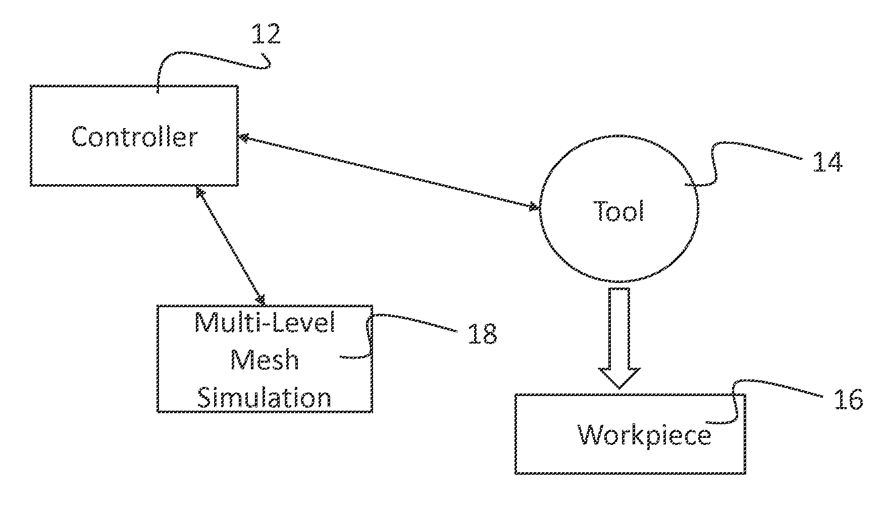
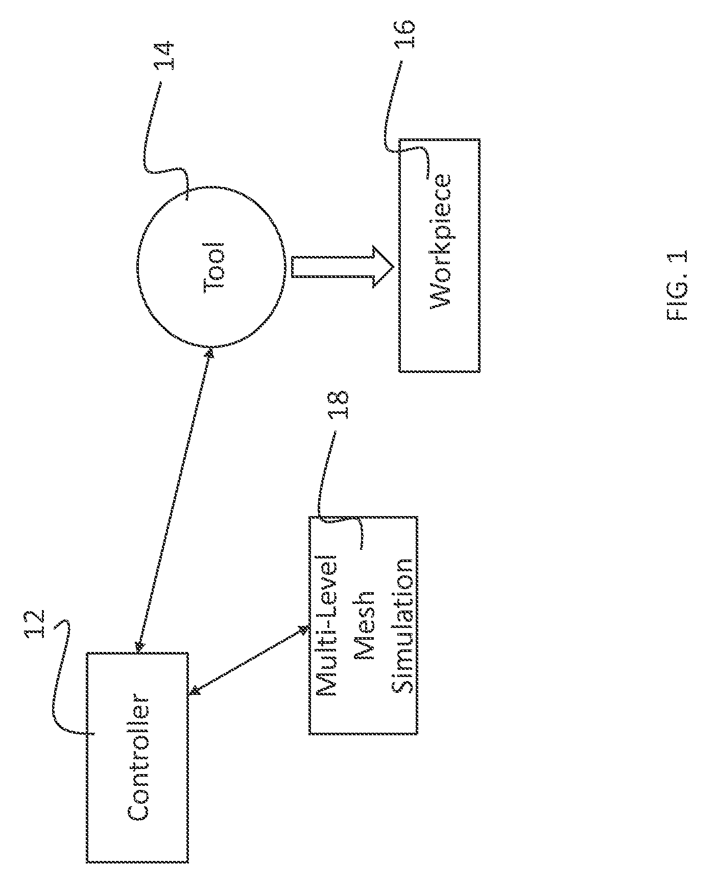
[0052]The invention has general applicability to modeling and control applications, and particularly closed loop control. Embodiments of the invention can model and control physical processes with high energy sources, such as themomechnical problems including a high energy source. Any physical process including a high energy source, e.g., a laser, that creates a localized anomaly can be modeled and controlled in real time through preferred embodiment modeling and control methods. Other applications include, for example, friction surfacing based solid state additive manufacturing which is another moving point energy source problem (though the material is heated below the melting point). Other areas of interest could be line and surface energy sources such as ultrasonic consolidation and photopolymer UV light exposure, and weapon systems that use high energy power beams.

[0053]Preferred embodiments provide methods for formulating and solving multi-scale moving meshes. Multi-scale simul...


PUM

PropertyMeasurementUnit
areaaaaaaaaaaa
thermo-mechanical stiffnessaaaaaaaaaa
microstructuresaaaaaaaaaa

Abstract

Simulation systems, manufacturing systems, software products and controllers are provided with multi-scale modeling in which a coarse mesh and a fme mesh that models a stimulus are decoupled. The fine mesh can be moved within the coarse mesh with a cut and paste operation. The coarse mesh is updated by sparsely propagated effects through the coarse mesh. Simulations of the invention can be conducted in real-time, and be used as controllers in manufacturing systems, such as additive manufacturing systems. A number of efficient methods are provided for solving meshing determinations that arise from movement of a stimulus modeled within a fine mesh.

Description

PRIORITY CLAIM AND REFERENCE TO RELATED APPLICATION[0001]The application claims priority under 35 U.S.C. §119 from prior provisional application Ser. No. 61 / 918,475, which was filed Dec. 19, 2013. That application is incorporated by reference herein.FIELD[0002]Fields of the invention concern modeling and simulation software products. The invention is generally applicable to modeling perturbations caused by energy, such as thermal energy or mechanical energy. Particular example products are utilized for prediction of part characteristics when fabricated using manufacturing processes in general and additive manufacturing technologies in particular. Additional applications of the invention include closed loop control of manufacturing processes, optimization and control software, finite element modeling software products and product design software. The systems and software products mentioned herein are applicable to process modeling, material and space modelling, object and part behavi...

Claims


Application Information

Patent Timeline
Patent Type & Authority Applications(United States)
IPC IPC(8): G06F17/50B22F3/105B33Y50/02G05B19/4099B33Y30/00
CPCG06F17/5018G05B19/4099B33Y30/00B33Y50/02B22F2003/1057G05B2219/35134G05B2219/49007G06F2217/12B22F3/1055G06F2111/10G06F30/23Y02P10/25B22F10/80B22F12/90B22F10/28B22F10/36G06F2119/18
Inventor PAL, DEEPANKARPATIL, NACHIKETSTUCKER, BRENT
Owner UNIV OF LOUISVILLE RES FOUND INC
Learn More