
Barrier layer coatings for battery pouch cell seal

a barrier layer and battery technology, applied in the direction of batteries, cell components, sustainable manufacturing/processing, etc., can solve the problems of premature cell failure or performance degradation, complex and expensive, etc., to enhance the hydrophobic properties, reduce the diffusion of edgewise, and enhance the surface roughness

Active Publication Date: 2016-11-17
GM GLOBAL TECH OPERATIONS LLC
View PDF5 Cites 16 Cited by
  • Summary
  • Abstract
  • Description
  • Claims
  • Application Information

AI Technical Summary

Benefits of technology

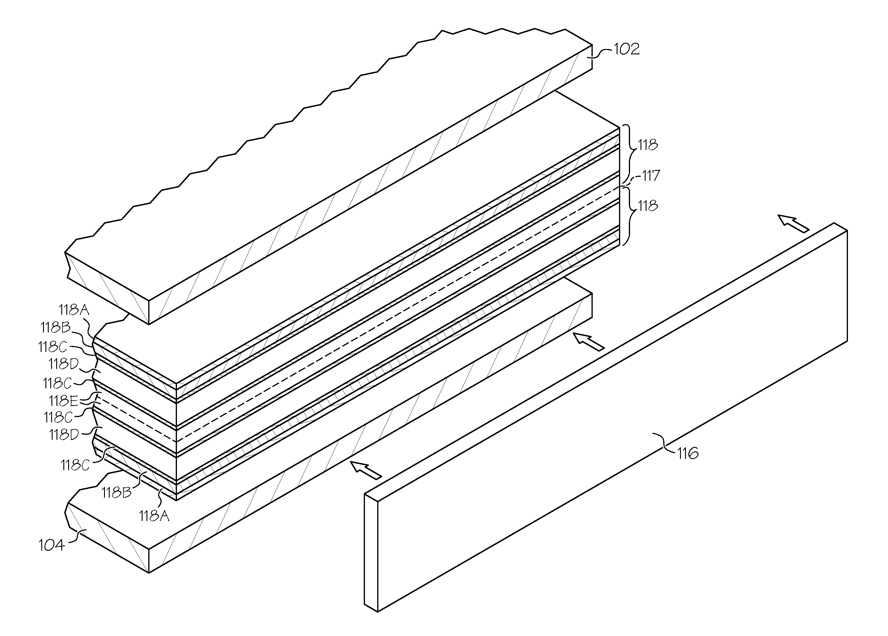
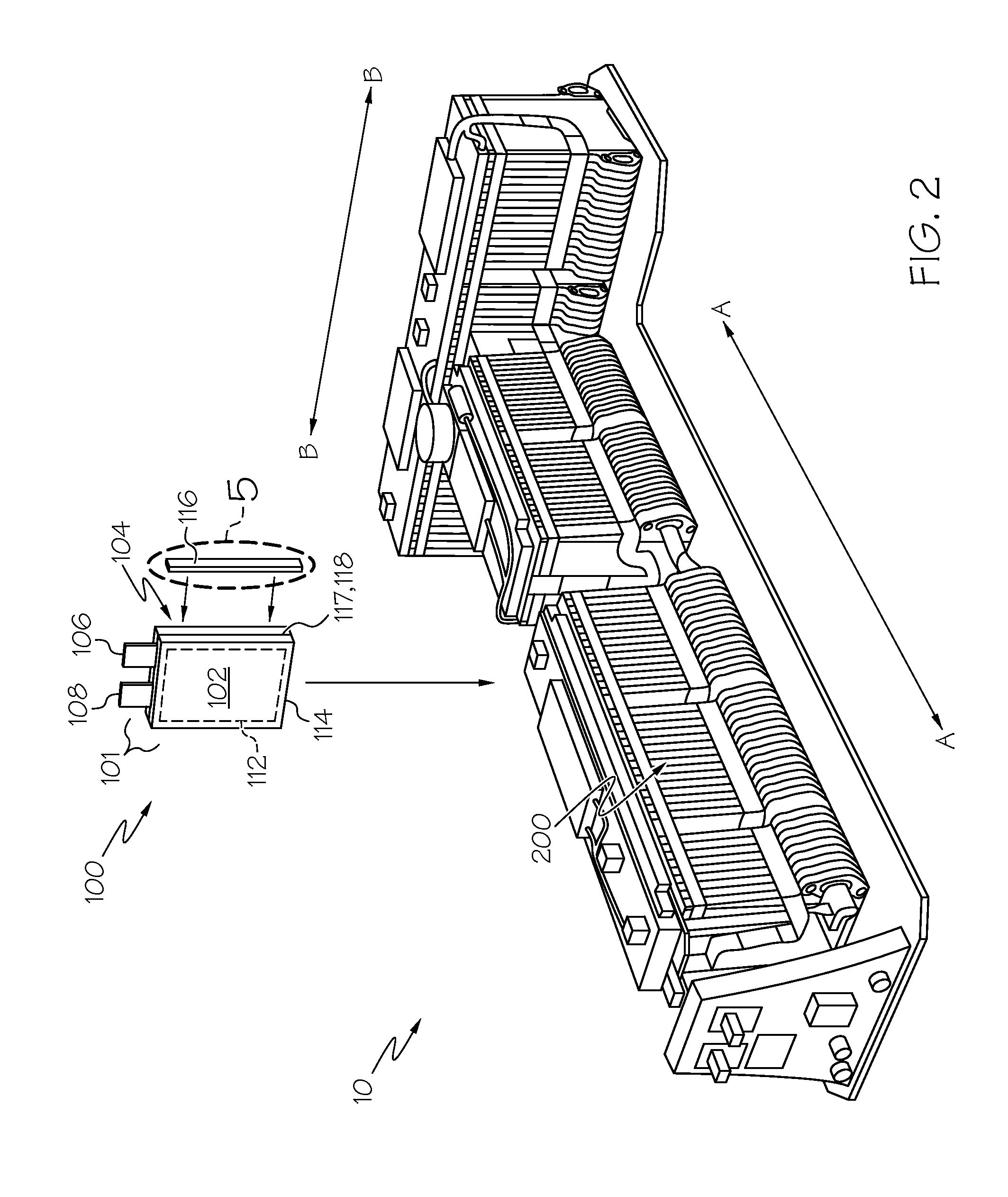
The patent text describes a new type of battery cell that uses a prismatic design and has tabs that protrude from the edges of the battery. The battery is surrounded by a containment made up of two facing surfaces that are joined together along seal areas. The seal areas have a barrier layer coating that is designed to prevent the diffusion of gases and liquids. The method of making the battery cell involves depositing a low permeability barrier layer coating over the seal areas and may also include additional treatment or layers to enhance its hydrophobic behavior. This design helps to improve the performance of the battery cell and make it more durable and reliable.

Problems solved by technology

The present inventors have determined that such heat seals (which may be made up of one or more layers of polypropylene, nylon, polyethylene and adhesive) do not provide protection against edgewise inward oxygen and water vapor permeation or edgewise outward electrolyte solvent vapor escape, and that either such phenomena can—if left unchecked—lead to premature cell failure or performance degradation.
Attempts to provide additional features to reduce susceptibility to such leakage are unavailing, as they are complex and expensive.

Method used


Image

  • Barrier layer coatings for battery pouch cell seal
  • Barrier layer coatings for battery pouch cell seal
  • Barrier layer coatings for battery pouch cell seal

Examples


Embodiment Construction

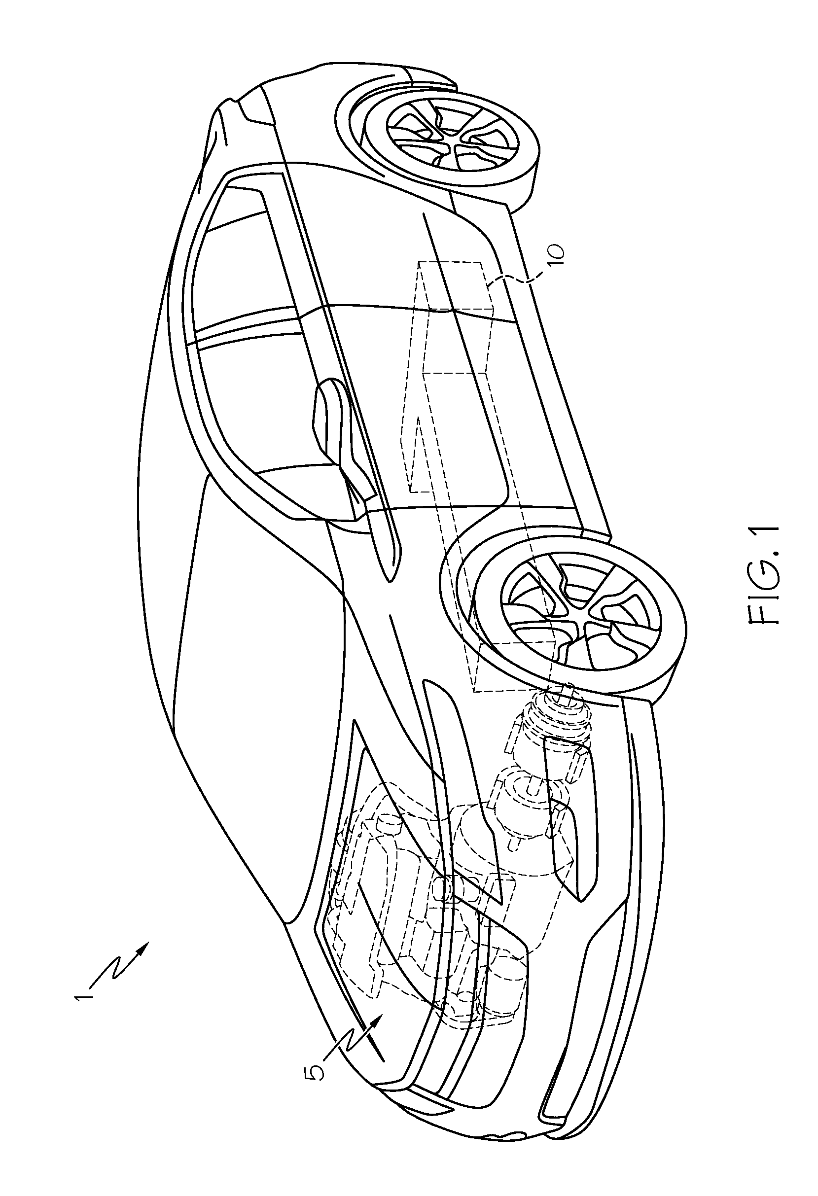
[0017]Referring first to FIG. 1, a vehicle 1 that can be used in conjunction with the present invention is shown. Vehicle 1 includes a hybrid propulsion system in the form of an electric power source made up of a conventional ICE 5 and a notional battery pack 10, both cooperative with one or more electric motors and transmission (for example, in the form of a planetary gear set) that makes up a drivetrain 15. Such a vehicle is known as a hybrid electric vehicle (HEV). It will be appreciated by those skilled in the art that vehicle 1 may not require an ICE 5, in such case, rather than being an HEV, it is an electric vehicle (EV); either form is within the scope of the present invention. As discussed elsewhere in the present disclosure, battery pack 10 may either be in the power battery pack or energy battery pack form, the particular variant becoming apparent from the context. Additional drivetrain components (none of which are shown) useful in providing propulsive power to one or mo...


PUM

PropertyMeasurementUnit
contact angleaaaaaaaaaa
thicknessaaaaaaaaaa
thicknessesaaaaaaaaaa

Abstract

A prismatic battery cell and a method of making such a cell. The cell includes one or more anode regions, one or more cathode regions, an electrolyte region to facilitate ion flow between the anode and cathode regions, electrically-conductive tabs attached to the corresponding anode and cathode regions, and a pouch-like containment formed around the regions. The containment is made up of a pair of facing substantially planar surfaces sealingly joined to one another. A barrier layer coating is made up of at least one low-permeability material and is placed over at least a portion of the cell edge that is defined by the joined surfaces such that the barrier layer coating blocks ambient gases or vapors from passing through the relatively gas-permeable heat seal region that is used to join the pouch surfaces. The barrier layer coating may also include one or more hydrophobic surface treatments or enhancements, including in one form an additional layer of surface treatments to funtionalize the surface and in another form by surface roughening.

Description

BACKGROUND OF THE INVENTION[0001]This invention relates generally to a way to improve the sealing of prismatic-shaped battery cells, and more particularly to the use of barrier layers made from extremely hydrophobic materials along the borders or edges of stacked planar battery cells as a way to improve corrosion resistance and reduced vapor permeability through the regions where adjacent cells are joined.[0002]Lithium-based batteries are being used in automotive and related transportation applications as a way to supplement, in the case of hybrid electric vehicles (HEVs), or supplant, in the case of purely electric vehicles (EVs), conventional internal combustion engines (ICEs). The ability to passively store energy from stationary and portable sources, as well as from recaptured kinetic energy provided by the vehicle and its components, makes such batteries ideal to serve as part of a propulsion system for cars, trucks, buses, motorcycles and related vehicular platforms. The flow ...

Claims


Application Information

Patent Timeline
Patent Type & Authority Applications(United States)
IPC IPC(8): H01M2/08H01M2/02H01M50/105H01M50/126H01M50/178H01M50/186H01M50/197H01M50/548H01M50/55H01M50/557
CPCH01M2/08H01M2220/20H01M2/0262H01M50/178H01M50/186H01M50/105H01M50/55H01M50/197H01M50/548H01M50/126Y02E60/10H01M50/124Y02P70/50
Inventor MACLEAN, GREGORY K.DADHEECH, GAYATRI VYAS
Owner GM GLOBAL TECH OPERATIONS LLC
Learn More