
Image reading method

a fluorescence image and image technology, applied in the field of fluorescence image reading, can solve the problems of difficulty in and achieve the effect of accelerating the detection process and reducing the volume of detection data

Inactive Publication Date: 2016-12-08
MITSUBISHI CHEM CORP
View PDF2 Cites 0 Cited by
  • Summary
  • Abstract
  • Description
  • Claims
  • Application Information

AI Technical Summary

Benefits of technology

This patent is about a method for capturing fluorescence images and determining when the imaging is complete or if a different condition should be set. By analyzing the intensity of the fluorescence in each region, the method can set optimal imaging conditions for each region and accelerate the detection process while reducing the volume of data. Overall, this patent improves the speed and accuracy of fluorescence image capture.

Problems solved by technology

Thus, even for a specimen that can be processed through dynamic range compensation of a single image, it is necessary to acquire images not to be used for detection.
Accordingly, it is quite difficult to accelerate the detection process and reduce the volume of detection data.

Method used


Image

  • Image reading method
  • Image reading method
  • Image reading method

Examples


Embodiment Construction

[0065]First, terms used in the present application are described.

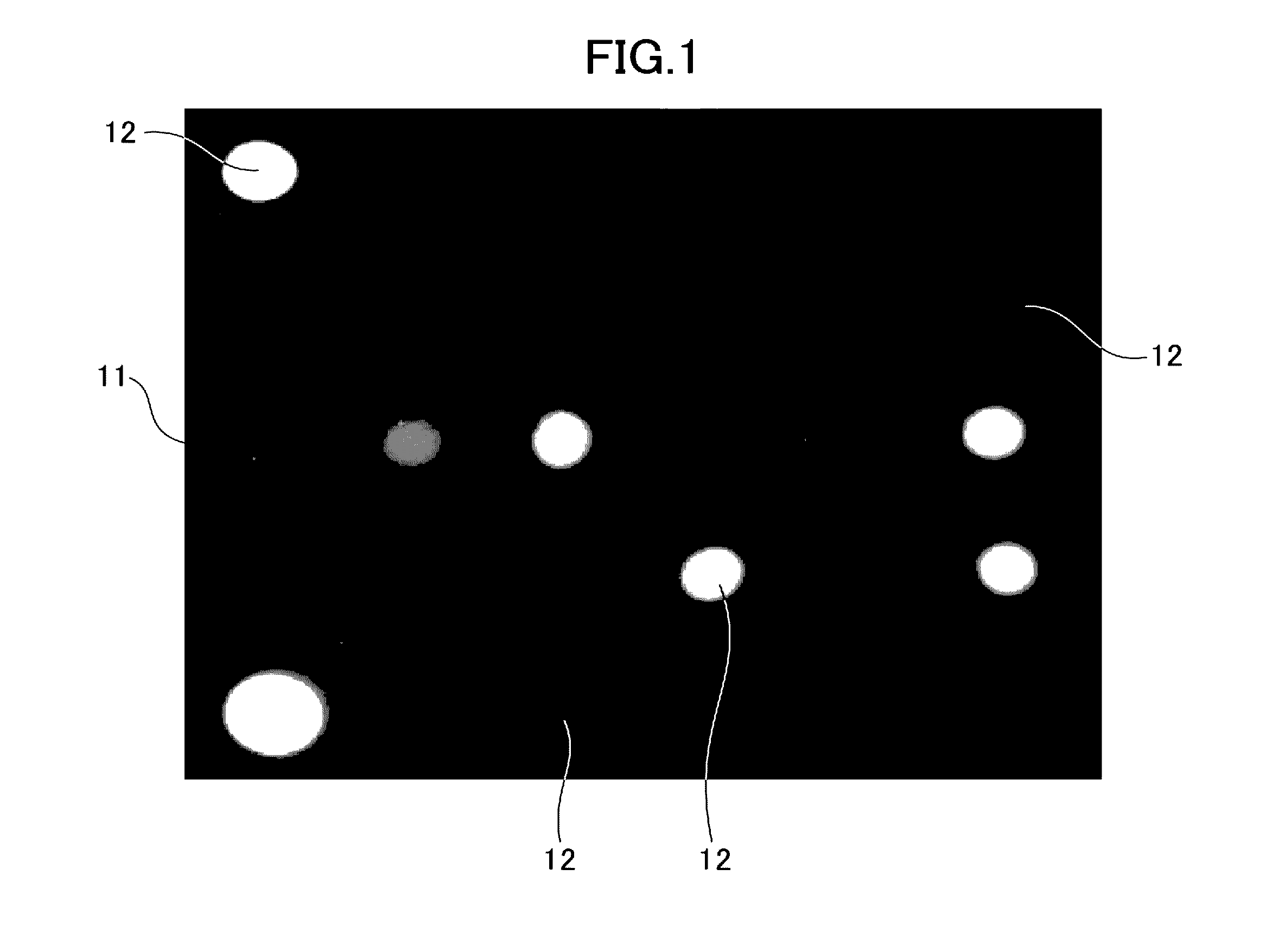
[0066]A fluorescence image of a biochip as shown in FIG. 1 corresponds to a specimen where multiple regions emit fluorescence, that is, an example of “a specimen where multiple regions are observed to emit fluorescence in different intensities.” In biochip 11, multiple regions 12 to emit fluorescence are arranged two-dimensionally, and the fluorescence emitted from each region varies in intensity from weak to strong. The size and shape of each region and the number and pitch of regions are not limited specifically.

[0067]As for a “biochip,” numerous probes are independently immobilized on a carrier to make a high-density array. A biochip is not limited to a specific type as long as probes (such as oligonucleotide probes) are immobilized on a carrier.

[0068]The type of biochip is not limited specifically, either; for example, a biochip shaped as a plate, rod, beads or the like may be used. When a planar carrier is used, p...


PUM

PropertyMeasurementUnit
timeaaaaaaaaaa
exposure timeaaaaaaaaaa
fluorescenceaaaaaaaaaa

Abstract

An image reading method realizing more rapid detection time and reduced volume of detection data during reading of fluorescence intensity from a fluorescence image that reads a fluorescence image from a sample in which a plurality of fluorescent regions are present, and includes: (a) setting a first image capture condition, (b) capturing a fluorescence image in the first image capture condition, (c) calculating a fluorescence intensity of each of plural regions in the captured fluorescence image, (d) determining whether to end image capture based on the calculated fluorescence intensities of the regions, (e) setting a next image capture condition based on the fluorescence intensities of the regions calculated in (c) when a decision is made in (d) not to end image capture, (f) capturing a fluorescent image in the next image capture condition, and (g) repeating (c) through (f) until a determination is made in (d) to end image capture.

Description

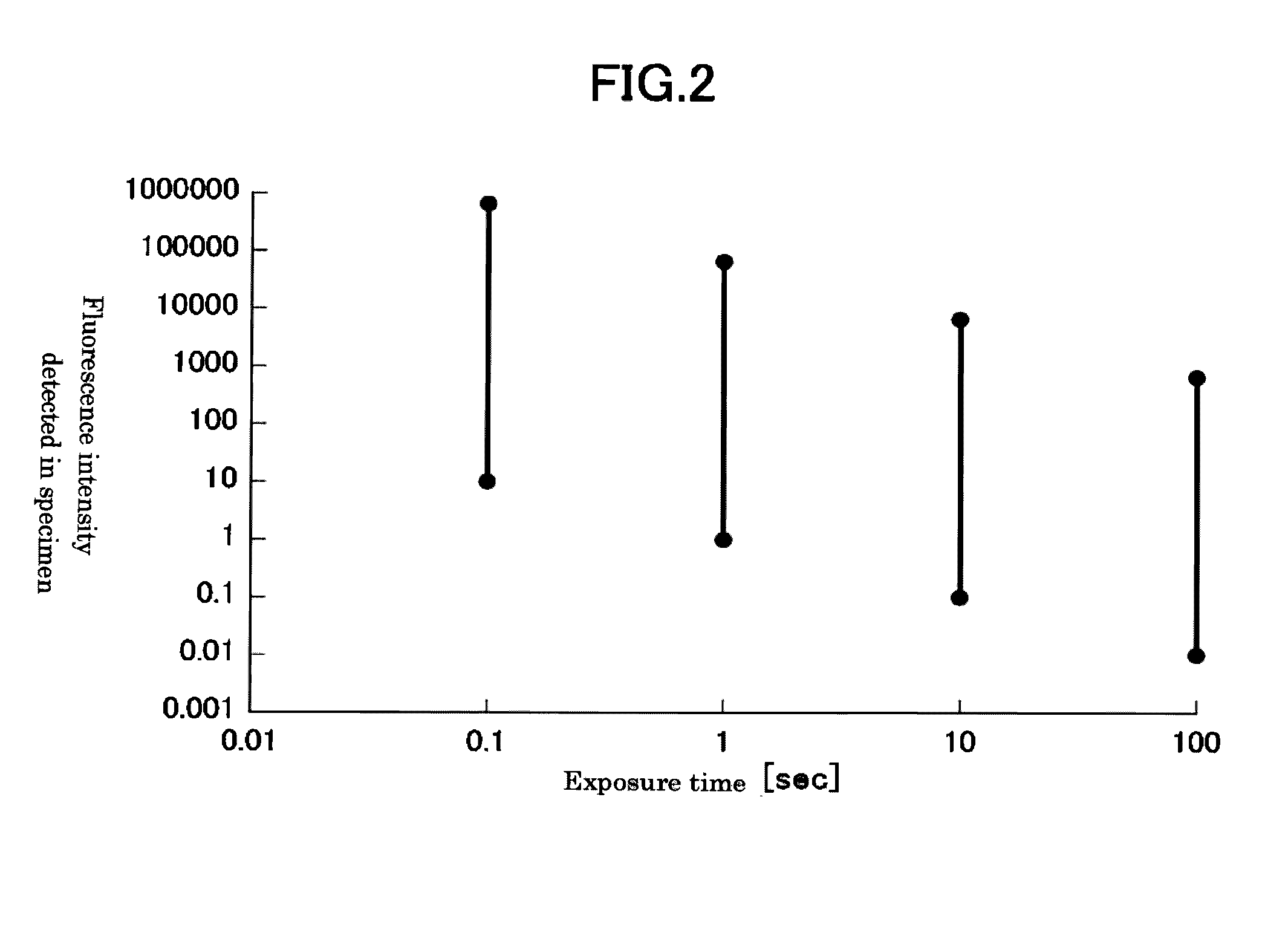
FIELD OF THE INVENTION[0001]The present invention relates to a method for reading fluorescence images of a specimen that contains multiple regions emitting fluorescence light at different intensities.BACKGROUND ART[0002]When fluorescence light is observed by using a fluorescence measurement device such as a laser scanner for fluorescence imaging or a fluorescence microscope, specimens may contain multiple regions emitting fluorescence light at various intensities in the observation range.[0003]Biochips are known as specimens where from some dozens to several tens of thousands of different bio-related materials such as DNA, proteins and antibodies as probes are immobilized. Intensities of fluorescence light detected in a biochip may vary in a wide range from weak to strong.[0004]When fluorescence images are scanned, a greater amount of information is usually obtained by setting a condition to receive more light.[0005]However, if the output intensity of excitation light and exposure c...

Claims


Application Information

Patent Timeline
Patent Type & Authority Applications(United States)
IPC IPC(8): G01N21/64G06T7/00
CPCG01N21/6458G06T2207/10064G06T7/0012G01N21/6456
Inventor SHIMIZU, KOUJI
Owner MITSUBISHI CHEM CORP
Learn More