
Impactor Spray Atmospheric Pressure Ion Source with Target Paddle

Active Publication Date: 2016-12-15
MICROMASS UK LTD
View PDF3 Cites 2 Cited by
  • Summary
  • Abstract
  • Description
  • Claims
  • Application Information

AI Technical Summary

Benefits of technology

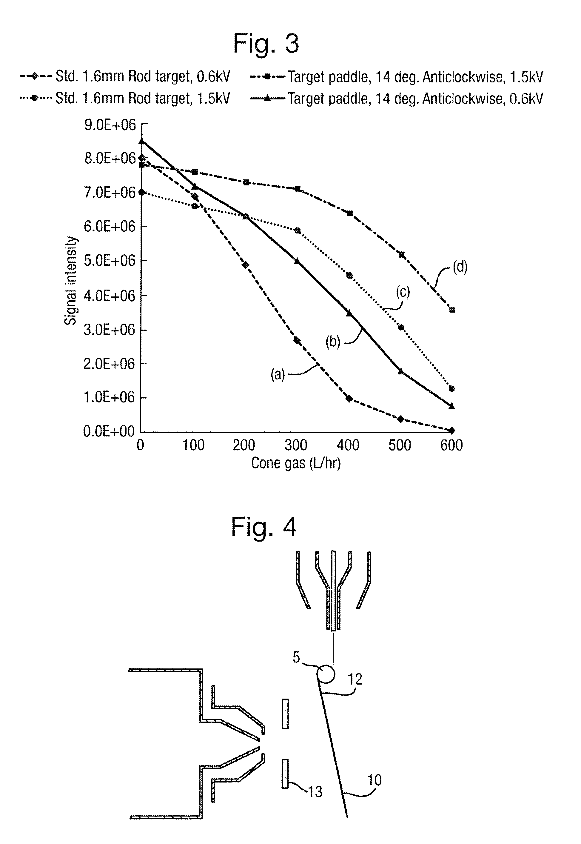
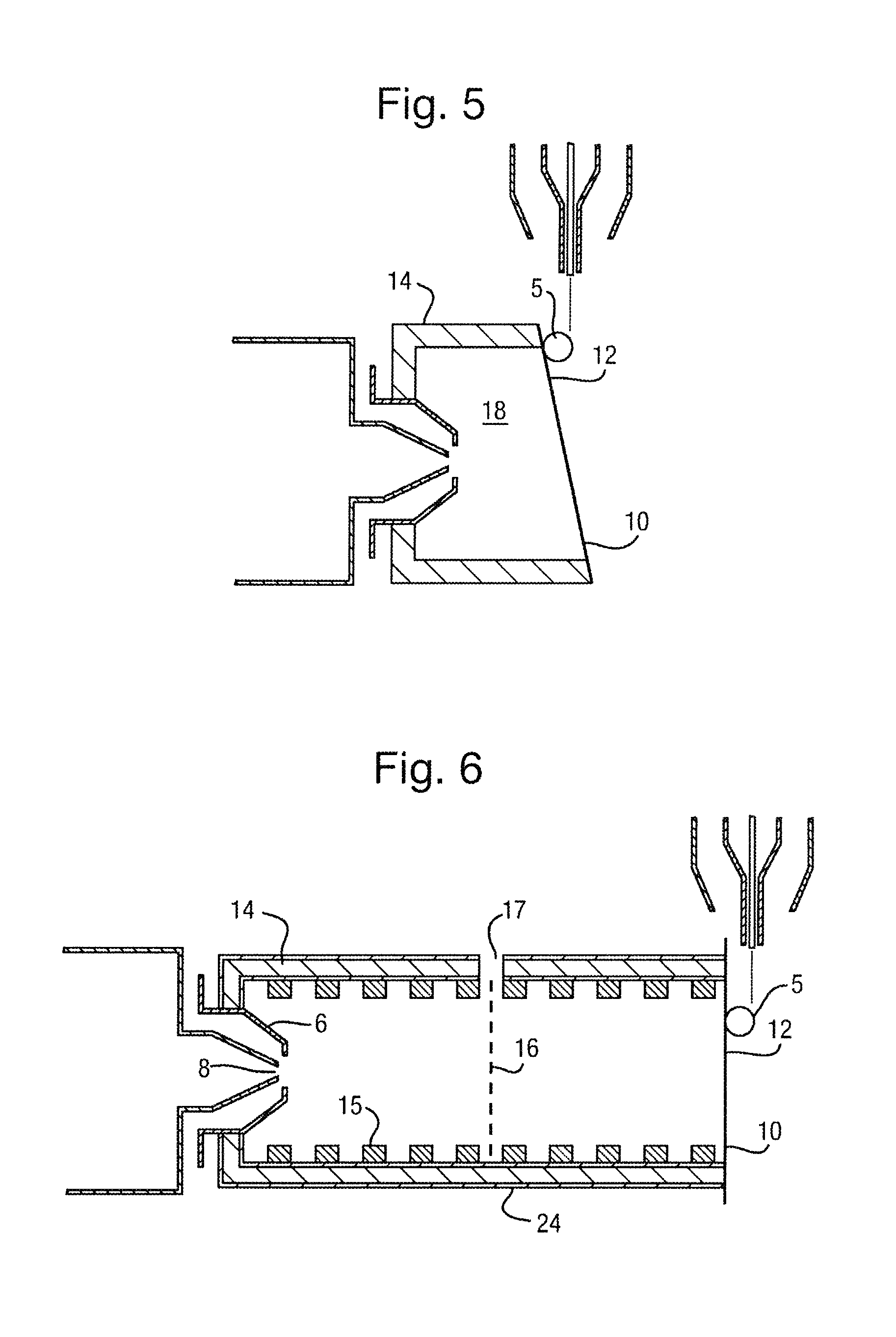
The invention is about improving the performance of an impactor ion source by using electrodes attached to the target. This helps to increase or shape the electric field between the target and the inlet to a mass spectrometer, resulting in better ion drift and less dispersive gas flow. The electrodes can be flat plate, paddle, or grid-shaped with exit apertures, notches, or cut-outs. By using these electrodes, the source can perform better even under high cone gas flow conditions and reduce contamination and chemical background. This invention is particularly advantageous for targets with a curved impact surface.

Problems solved by technology

A problem with the known arrangement is that if the cone gas flow is maintained at a flow rate which exceeds the flow of gas being drawn through the inlet into the first vacuum stage of the mass spectrometer then ion signal losses can become significant.
Accordingly, known impactor spray ion sources suffer from a loss of ion signal at high cone gas flow rates which is particularly problematic.

Method used


Image

  • Impactor Spray Atmospheric Pressure Ion Source with Target Paddle
  • Impactor Spray Atmospheric Pressure Ion Source with Target Paddle
  • Impactor Spray Atmospheric Pressure Ion Source with Target Paddle

Examples


Embodiment Construction

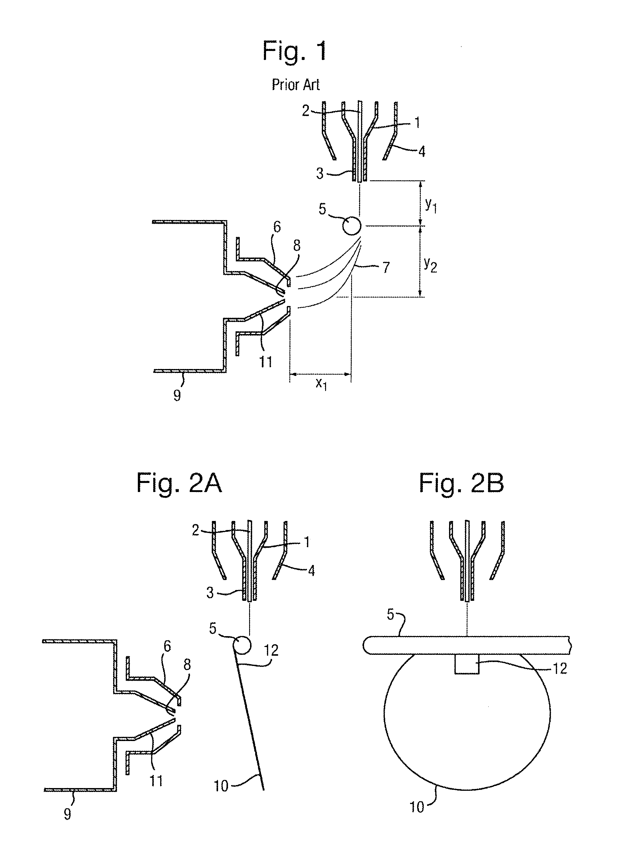
[0125]A known impactor ion source will first be described with reference to FIG. 1.

[0126]FIG. 1 shows a known impactor spray source comprising a pneumatic nebuliser assembly 1, a desolvation heater 4 which surrounds the nebuliser 1 and an impactor target 5 arranged downstream of the nebuliser 1. An inlet to a mass spectrometer is also shown. The inlet preferably comprises an ion inlet device comprising a cone gas nozzle 6 and an ion inlet orifice 8 formed within an ion inlet cone 11.

[0127]A first vacuum region 9 of the mass spectrometer is shown downstream of the ion inlet cone 11. The arrangement may be surrounded by an electrically grounded source enclosure (not shown) that contains an exhaust outlet for the venting of solvent fumes.

[0128]The nebuliser assembly 1 comprises an inner liquid capillary 2 and an outer gas capillary 3 that delivers a high velocity stream of gas at the nebuliser tip to aid the atomization of the liquid solvent flow.

[0129]The inner liquid capillary 2 typi...


PUM


Abstract

An ion source is provided comprising one or more nebulisers and one or more targets, wherein the one or more nebulisers are arranged and adapted to emit, in use, a stream predominantly of droplets which are caused to impact upon the one or more targets and to ionise the droplets to form a plurality of ions. The ion source further comprises one or more electrodes arranged adjacent to and / or attached to the one or more targets wherein the one or more electrodes comprise one or more apertures, notches or cut-outs wherein at least some of the plurality of ions pass, in use, through the one or more apertures, notches or cut-outs.

Description

CROSS-REFERENCE TO RELATED APPLICATION[0001]This application claims priority from and the benefit of United Kingdom patent application no. 1403370.8 filed on 26 Feb. 2014 and European patent application no. 14156845.1 filed on 26 Feb. 2014. The entire contents of these applications are incorporated herein by reference.BACKGROUND TO THE PRESENT INVENTION[0002]The present invention relates to an ion source, a mass spectrometer, a method of ionising ions and a method of mass spectrometry.[0003]Impactor spray atmospheric pressure ionisation (“API”) ion sources are known and comprise an arrangement wherein a heated, high velocity liquid spray is emitted from a nebuliser and is directed so as to impact upon a small cylindrical rod target that is held at a relatively high potential with respect to the nebuliser. The resulting plume from the target is then sampled into the first vacuum stage of a mass spectrometer for subsequent mass analysis.[0004]Conventional atmospheric pressure ionisati...

Claims


Application Information

Patent Timeline
IPC IPC(8): H01J49/04H01J49/14H01J49/00
CPCH01J49/045H01J49/142H01J49/0031H01J49/0445H01J49/16
Inventor BAJIC, STEVAN
Owner MICROMASS UK LTD
Learn More