Sampling/Quantization Converters

a converter and sampling/quantization technology, applied in the field of sampling/quantization converters, to achieve the effect of reducing the output of level detectors, high resolution, and better combination

Active Publication Date: 2016-12-22
PAGNANELLI FAMILY TRUST
View PDF0 Cites 41 Cited by
  • Summary
  • Abstract
  • Description
  • Claims
  • Application Information

AI Technical Summary

Benefits of technology

[0025]Another embodiment is directed to an apparatus for calibrating the noise transfer function of a bandpass quantization-noise-shaping circuit. The apparatus preferably includes: (a) a first input line for accepting a high-resolution (or at least relatively high-resolution) version of an input signal, (b) a second input line for accepting a low-resolution (or at least a relatively lower-resolution, e.g., coarsely-quantized) version of the input signal, (c) a quantization noise estimator, which is coupled to the first and second input lines, and which preferably generates a high-resolution error signal that in a particular frequency band, is proportional to the difference between the high-resolution input signal and the coarsely-quantized version of the input signal; (d) a quantization element that is coupled to the output of the quantization noise estimator and converts the high-resolution error signal into a preferably coarsely-quantized error signal; (e) a downconverter (e.g., downsampler) which is coupled to the output of the quantization element and which converts the coarsely-quantized error signal from an original frequency band to baseband (i.e., generates a baseband version of the coarsely-quantized error signal); (f) a level detector which is coupled to the output of the downconverter and measures a property of the baseband error signal which is indicative of signal strength, such as amplitude or power; and (g) an adaptive control component coupled to the output of the level detector. Before downconversion to baseband, the original frequency band of the error signal typically is centered at a frequency which is equal to, or is at least approximately equal to, a frequency coinciding with an intended spectral minimum in the noise transfer function of the bandpass quantization-noise-shaping circuit. The adaptive control component preferably minimizes the level detector output by adjusting a parameter within the bandpass quantization-noise-shaping circuit.
[0026]According to

Problems solved by technology

However, existing solutions are limited by instantaneous bandwidth (effective sample rate), effective conversion resolution (number of effective bits), or both.
When a continuous-time continuously variable signal is converted into a discrete-time discretely variable signal through sampling and quantization, the quality of the signal degrades because the conversion process introduces quantization, or rounding, noise.
However, the resolution of flash converters can be limited by practical implementation impairments that introduce quantization errors, such as clock jitter, thermal noise, and rounding/gain inaccuracies caused by component tolerances.
Although flash converters potentially could realize high resolution at instantaneous bandwidths greater than 10 GHz, this potential has been unrealized in commercial offerings.
However, pipelined converters typically can provide less than about 1 GHz of instantaneous bandwidth.
The error-feedback structure is conventionally considered suitable for digital implementations (i.e., digital-to-analog conversion), but not for analog implementations due to its increased sensitivity to component mismatches compared to the interpolative structure.
Conventional oversampling converters can offer very high resolution, but the noise shaping and signal reconstruction process generally limits the utility of oversampling converters to applications requiring only low instantaneous bandwidth.
These disadvantages, which are discussed in greater detail in the Description of the Preferred Embodiment(s) section, include: 1) use of delta-sigma modulation (Galton, Aziz, and Beydoun) impairs high-frequency operation because the sample-and-hold function limits the performance of DT ΔΣ modulators and non-ideal circuit behavior can degrade the noise-shaped response and stability of CT ΔΣ modulators; 2)

Method used


Image

  • Sampling/Quantization Converters
  • Sampling/Quantization Converters
  • Sampling/Quantization Converters

Examples


Embodiment Construction

)

[0054]The present disclosure is related to the disclosure set forth in the application by the present inventor, titled “Multimode Sampling / Quantization Converters”, which is being filed on the same day as the present application. The foregoing application is incorporated by reference herein as though set forth herein in full.

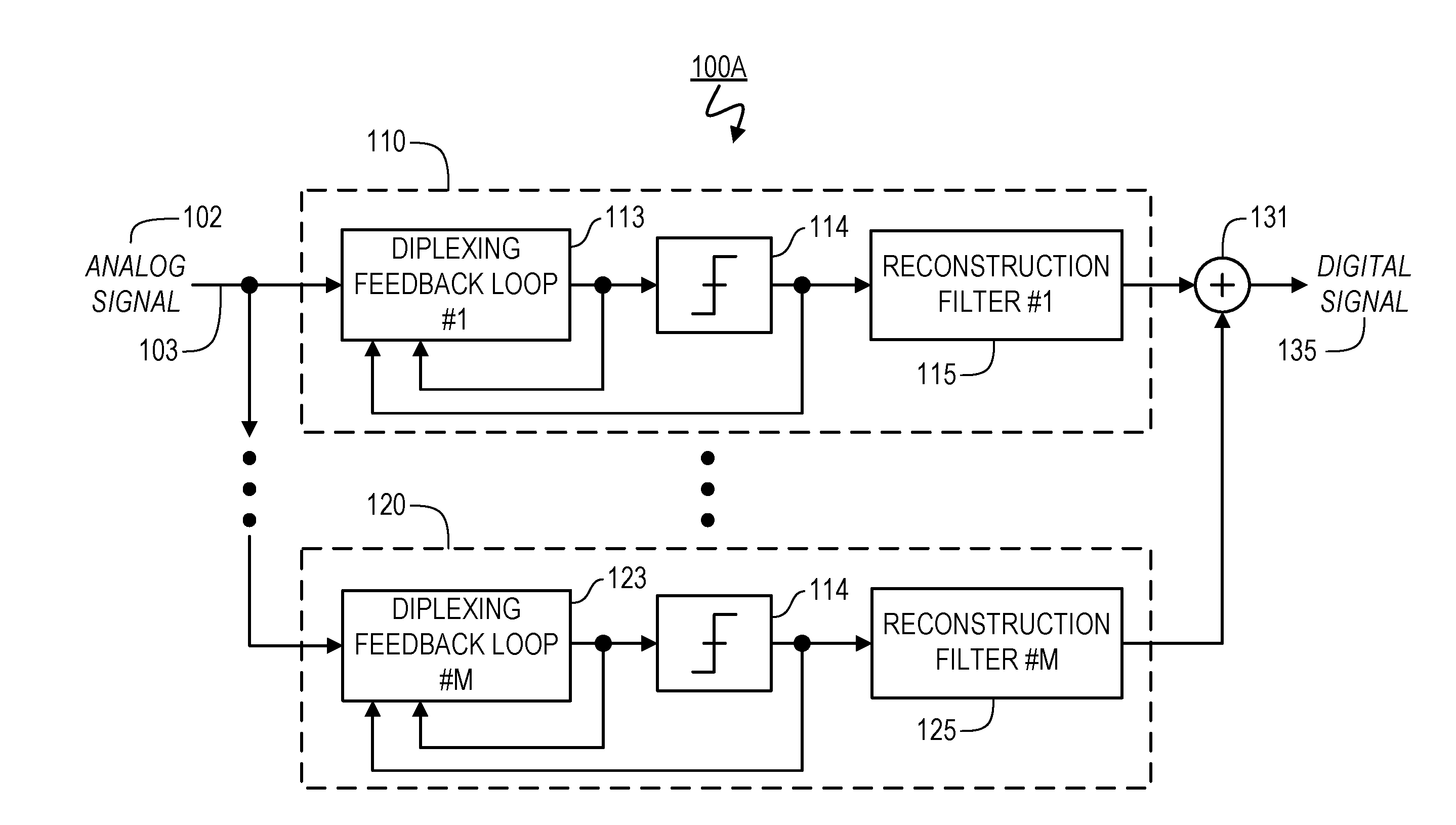
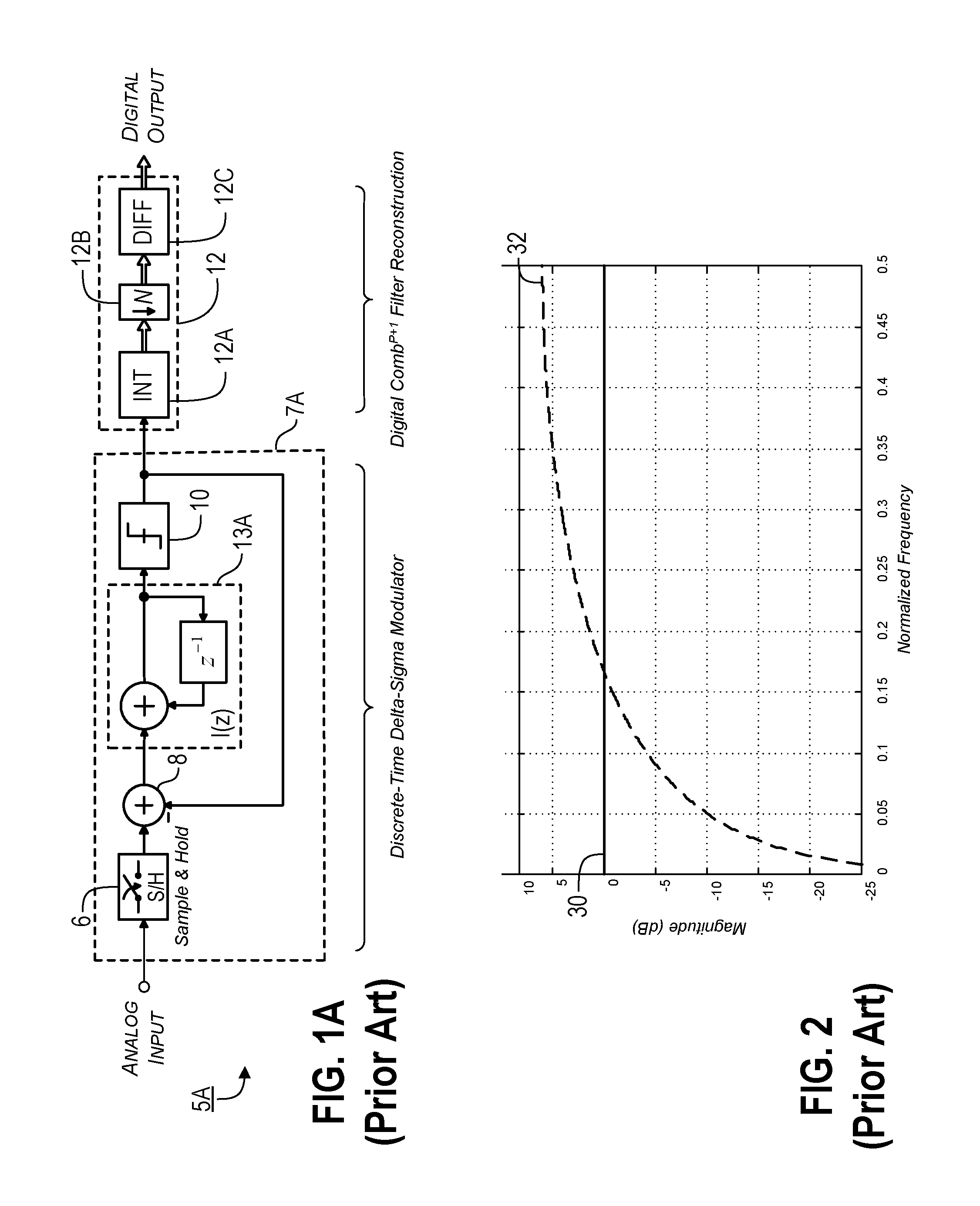
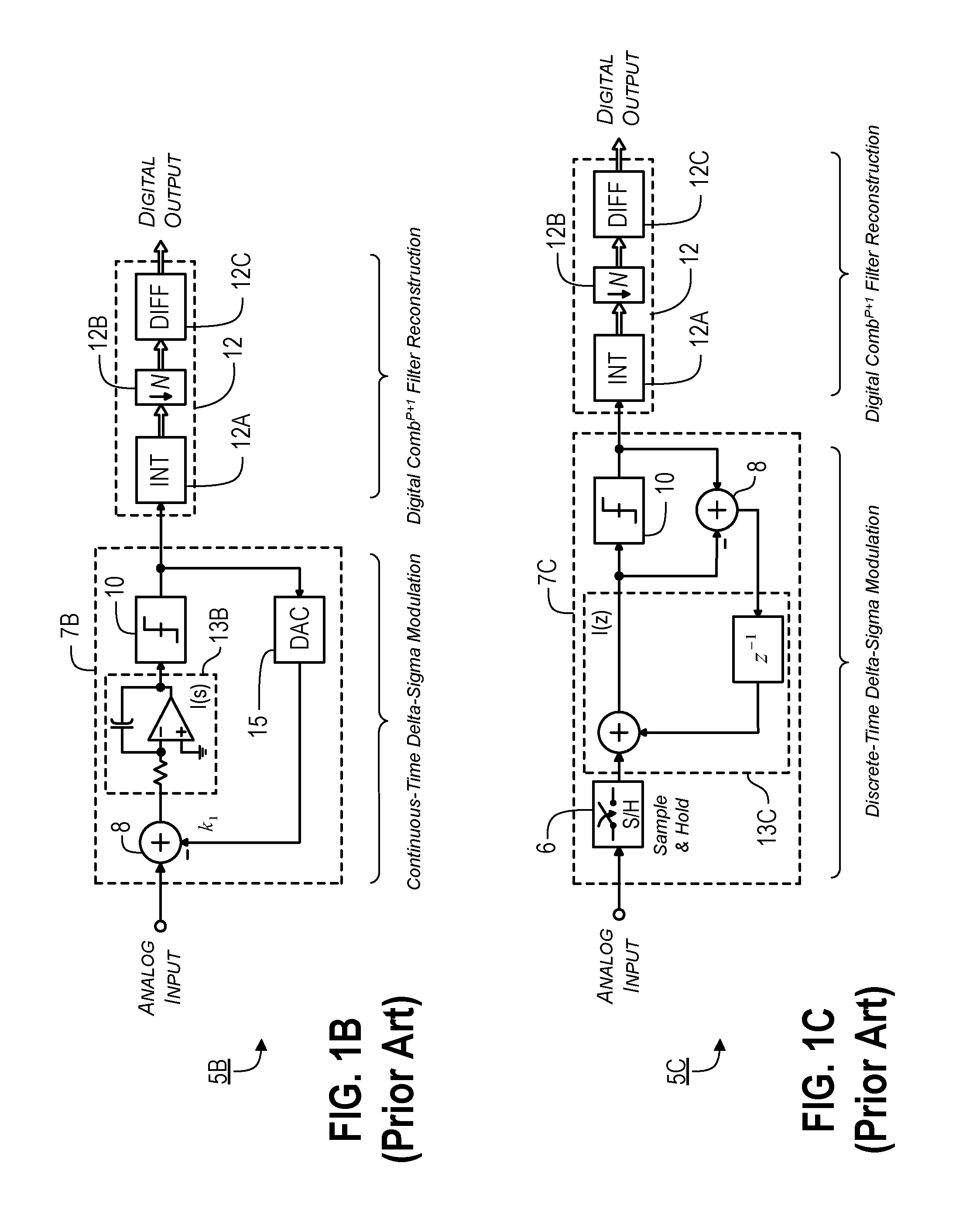
[0055]A preferred converter according to the present invention uses a technique that sometimes is referred to herein as Multi-Channel Bandpass Oversampling (MBO). Such a technique shares some structural similarities with conventional parallel delta-sigma (ΠΔΣ) and multiband delta-sigma (MBΔΣ) analog-to-digital converters, in that the MBO converter also consists of multiple, parallel, oversampling converters. However, a MBO converter according to the preferred embodiments of the present invention incorporates one or more of the following technological innovations to improve instantaneous bandwidth and resolution: 1) continuous-time, Diplexing Feedback Loops (DFL...


PUM


Abstract

Provided are, among other things, systems, apparatuses, methods and techniques for converting a continuous-time, continuously variable signal into a sampled and quantized signal. One such apparatus includes an input line for accepting an input signal that is continuous in time and continuously variable, multiple processing branches coupled to the input line, and an adder coupled to outputs of the processing branches, with each of the processing branches including a bandpass noise-shaping circuit, a sampling/quantization circuit coupled to an output of the bandpass noise-shaping circuit, a digital bandpass filter coupled to an output of the sampling/quantization circuit, and a line coupling an output of the sampling/quantization converter circuit back into the bandpass noise-shaping circuit. A center frequency of the digital bandpass filter in each processing branch corresponds to a stopband region in a quantization noise transfer function for the bandpass noise-shaping circuit in the same processing branch.

Description

[0001]This application is a continuation in part of i) U.S. patent application Ser. No. 15 / 209,711 (filed Jul. 13, 2016) which, in turn, is a continuation in part of U.S. patent application Ser. No. 14 / 818,502 (filed Aug. 5, 2015, now U.S. Pat. No. 9,419,637); and ii) U.S. patent application Ser. No. 14 / 944,182 (filed Nov. 17, 2015) which, in turn, claims the benefit of U.S. Provisional Patent Application Ser. Nos. 62 / 133,364 (filed Mar. 14, 2015) and 62 / 114,689 (filed Feb. 11, 2015). The present application also claims the benefit of U.S. Provisional Patent Application Ser. No. 62 / 213,231 (filed Sep. 2, 2015).[0002]The present application also is related to: U.S. patent application Ser. No. 14 / 567,496, filed on Dec. 11, 2014, U.S. patent application Ser. No. 13 / 363,517 (the '517 Application), filed on Feb. 1, 2012 (now U.S. Pat. No. 8,943,112), U.S. patent application Ser. No. 12 / 985,238, filed on Jan. 5, 2011 (now U.S. Pat. No. 8,299,947), U.S. Provisional Patent Application Ser. ...

Claims


Application Information

Patent Timeline
IPC IPC(8): H03M1/06H03M3/00H03M1/34
CPCH03M1/0626H03M1/34H03M3/414H03M3/38H03M3/322H03M3/468H03M3/404H03M3/422H03M3/436
Inventor PAGNANELLI, CHRISTOPHER
Owner PAGNANELLI FAMILY TRUST
Why Eureka
Try Eureka