Stress and temperature compensated hall sensor, and method
What is AI technical title?
AI technical title is built by Patsnap AI team. It summarizes the technical point description of the patent document.
a hall sensor and temperature compensation technology, applied in the field of stress and temperature compensation hall sensors, can solve the problems of inconvenient operation, inability to adjust the temperature of the sensor, etc., and achieve the effect of flexible and accurate, and relatively easy implementation
Active Publication Date: 2016-12-29
MELEXIS TECH NV
View PDF6 Cites 19 Cited by
Summary
Abstract
Description
Claims
Application Information
AI Technical Summary
This helps you quickly interpret patents by identifying the three key elements:
Problems solved by technology
Method used
Benefits of technology
Benefits of technology
The present invention provides a compensation method that is easier to perform and a device that is easier to produce. The method described in the patent text requires less power and resources, and can be performed faster than existing methods. This allows for more efficient and effective compensation in various applications.
Problems solved by technology
There are however several problems related to the readout of a Hall sensor:1a) the Hall-voltage is typically very small (typically in the microvolt to millivolt range) hence needs to be amplified, but both Hall element and amplifiers may have an offset (the output of the amplifier is non-zero in the presence of a zero magnetic field).
This problem is typically addressed in the prior art by measuring the offset-voltage in a calibration (during production), storing the measured value in a non-volatile memory in the device, and retrieving the stored value and subtracting it from the output of the amplifier during actual use of the device;1b) Another problem is that this offset is not constant over time, but drifts.
If mechanical stress would not change over time, this problem could be easily solved by the calibration test, but unfortunately, mechanical stress varies over time, inter alia because of moisture in the packaging.
Such a direct approach is very complex.
Method used
Image
Click on the blue label to locate the original text in one second.
Reading with bidirectional positioning of images and text.
Examples
example 1
[0193]In a first example, the following correction factor CF is used:
As described above, the values of γ00, γ20, γ11, γ02, γ10, γ01, may be determined during production (e.g. after packaging or after probing), and can be stored in a non-volatile memory, physically connectable or physically embedded in the device.
example 2
[0194]In a variant of example 1, some of the coefficients are chosen equal to zero, resulting in less coefficients to be determined and stored, and a simpler formula to be calculated. The correction factor of the second example is:
[0195]The third example is actually the same as the second example, but formulated differently. The main reason of this example is to show that the polynomial representation can also be used to represent “coefficients that are temperature-dependent”. The equation [23] can be rewritten as:
CF=(γ00+(γ10+γ11·ΔT)·Δσiso+γ02·ΔT̂2+γ01·ΔT) [25]
or:
CF=(γ00+λ1·Δσiso+γ02·ΔT̂2+γ01·ΔT) [26]
where the value of λ1 is not constant, but is temperature-dependent, and can be stored in the non-volatile memory as a list of values, e.g. representing a piece-wise linear approximation, along with the coefficients γij.
[0196]From this example it shall be clear that the formulation of the correction factor as a polynomial, can thus also represent temperature-dependent coefficients, even though the coefficients γij are constants.
PUM
Abstract
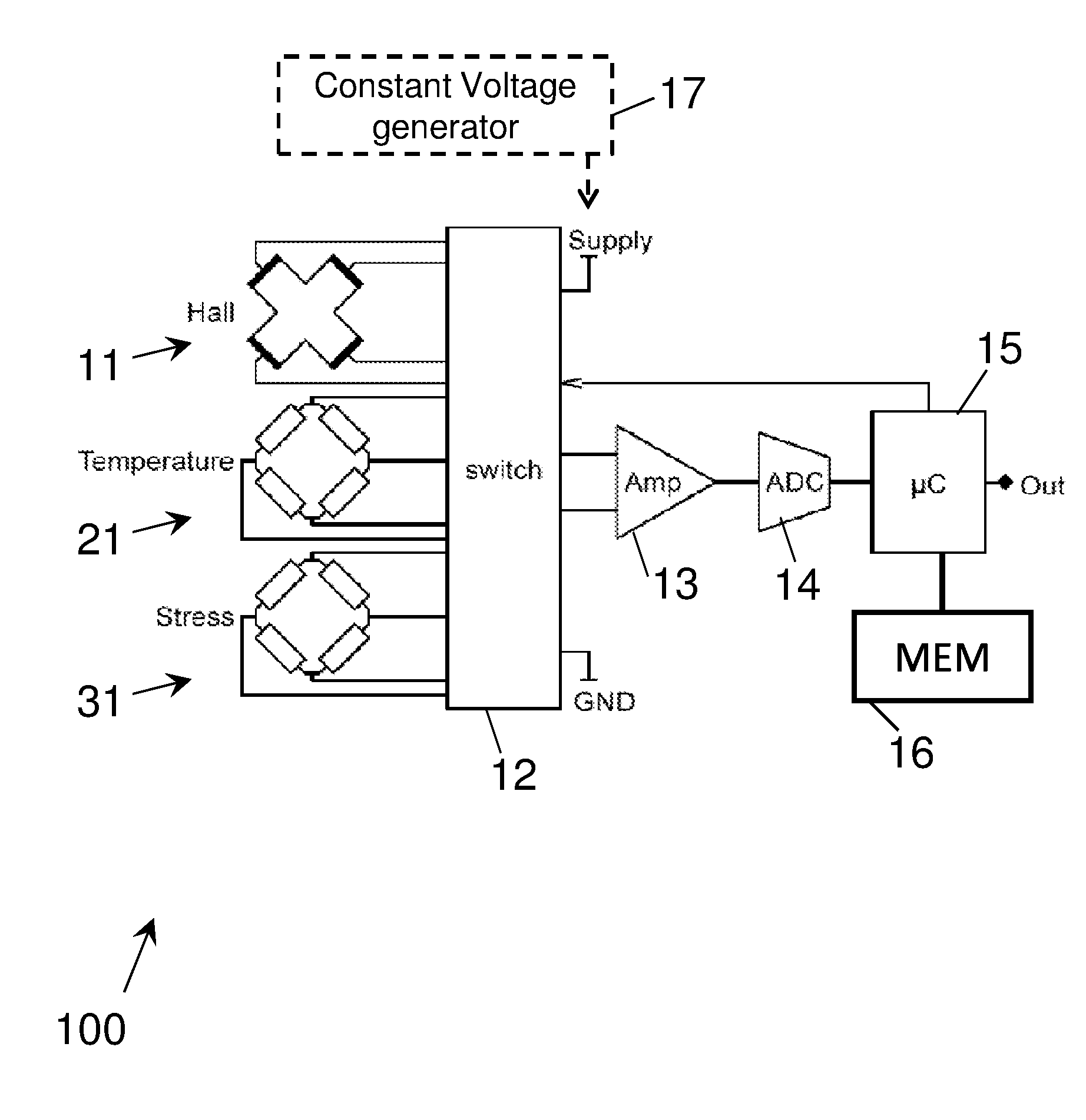
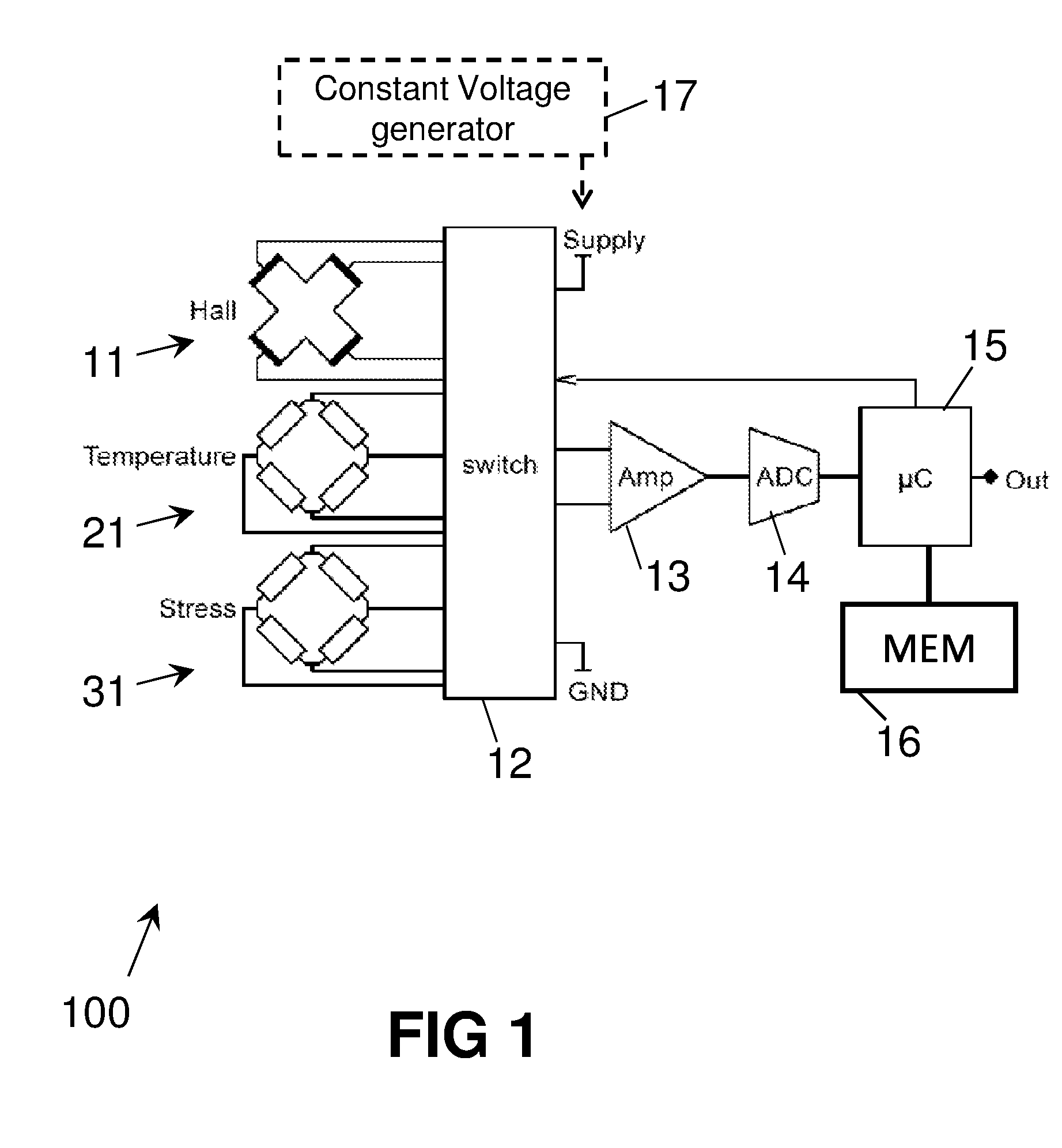
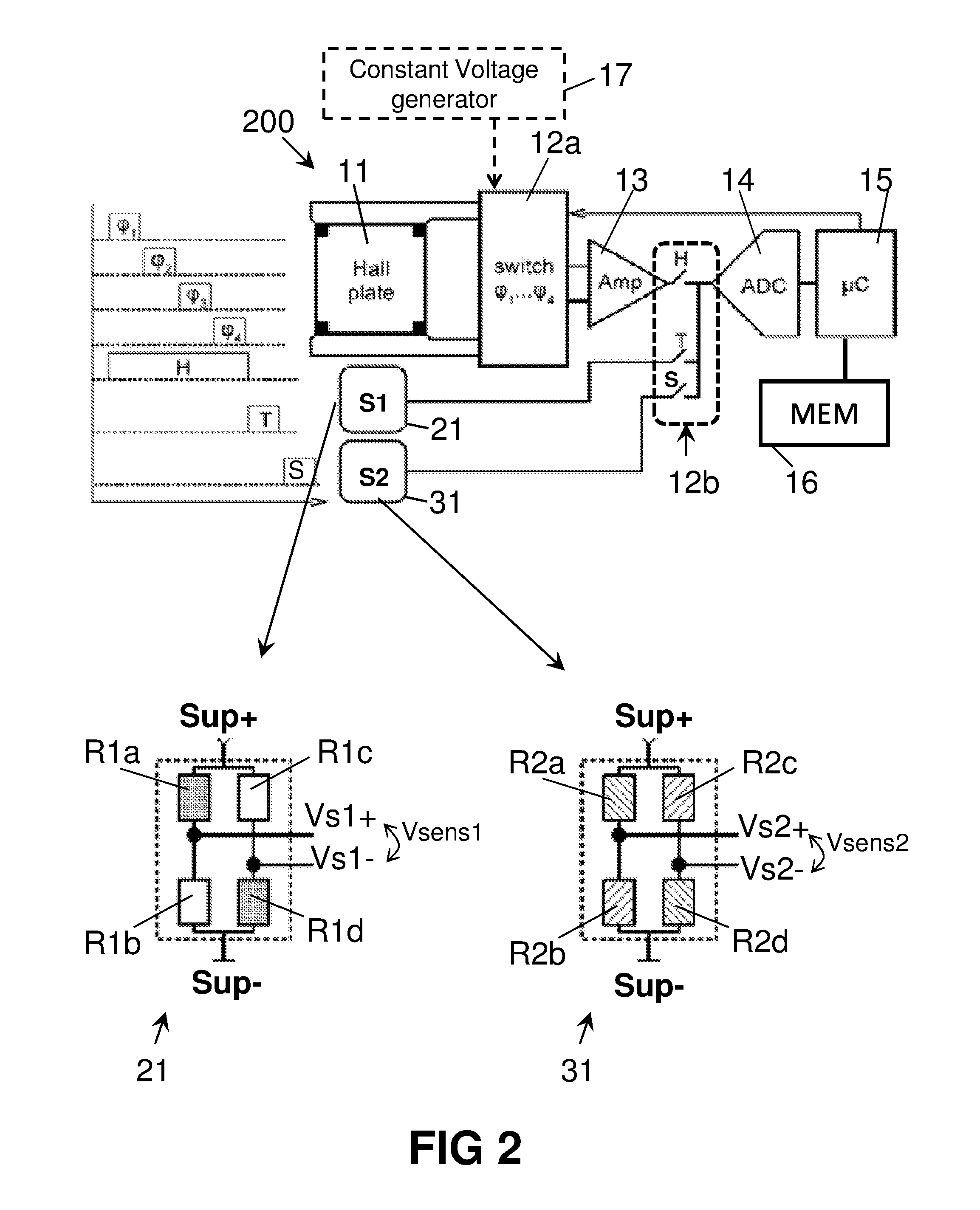
An integrated semiconductor device for measuring a magnetic field, comprising: a Hall sensor, a first lateral isotropic sensor having a first stress sensitivity and a first temperature sensitivity, a second lateral isotropic sensor having a second stress sensitivity and a second temperature sensitivity, optional amplifying means, digitization means; and calculation means configured for calculating a stress and temperature compensated Hall value in the digital domain, based on a predefined formula which can be expressed as an n-th order polynomial in only two parameters. These parameters may be obtained directly from the sensor elements, or they may be calculated from a set of two simultaneous equations. A method of obtaining a Hall voltagesignal, and compensating said signal for stress and temperature drift.
Description
FIELD OF THE INVENTION[0001]The present invention relates in general to the field of integrated Hall sensors, and in particular to the field of integrated Hall sensors which are compensated for temperature and for mechanical stress. The present invention also relates to a method of compensating a Hall sensor readout for both mechanical stress and temperature.BACKGROUND OF THE INVENTION[0002]The basic functionality of a Hall sensor is to measure the magnitude of a magnetic field, based on the so called “Hall-effect”, whereby a voltage is generated over a conductor (e.g. a conductive plate) when a current is flowing through said conductor in the presence of a magnetic field. This phenomenon is well known in the art, and hence need not be further explained here.[0003]There are however several problems related to the readout of a Hall sensor:[0004]1a) the Hall-voltage is typically very small (typically in the microvolt to millivolt range) hence needs to be amplified, but both Hall eleme...
Claims
Application Information
Patent Timeline
Application Date:The date an application was filed.
Publication Date:The date a patent or application was officially published.
First Publication Date:The earliest publication date of a patent with the same application number.
Issue Date:Publication date of the patent grant document.
PCT Entry Date:The Entry date of PCT National Phase.
Estimated Expiry Date:The statutory expiry date of a patent right according to the Patent Law, and it is the longest term of protection that the patent right can achieve without the termination of the patent right due to other reasons(Term extension factor has been taken into account ).
Invalid Date:Actual expiry date is based on effective date or publication date of legal transaction data of invalid patent.
Patent Type & AuthorityApplications(United States)

