
Neck-wearable communication device with microphone array

a communication device and microphone array technology, applied in the field of telecommunication devices, can solve the problems of slack cords, difficult to wear headsets under clothing, earphone storage structures, etc., and achieve the effect of preventing substantial changes in user appearance, convenient use, and no restriction of user's movement freedom

Active Publication Date: 2016-12-29
USHAKOV ALEXEY LEONIDOVICH
View PDF2 Cites 46 Cited by
  • Summary
  • Abstract
  • Description
  • Claims
  • Application Information

AI Technical Summary

Benefits of technology

The patent text discusses a problem with traditional neck loops for wearing electronic devices on the user's neck. O-shaped loops can be difficult to put on and take off, while U-shaped loops provide a more comfortable fit but may not be convenient for women-targeted devices. The patent also describes a solution for reducing noise in speech signals when using wearable devices. This is achieved by placing a microphone close to the user's mouth, but this causes usability issues and requires a support structure. A more convenient option is the use of a dual-port microphone positioned on the user's chest, which can effectively cancel out noise but requires accurate distance between the microphone and the user's mouth. The patent proposes a new wearable device with an U-shaped neck-wearable housing that allows for easy put-on and take-off and provides a compact design for noise reduction.

Problems solved by technology

The headset comprises long unsecured portions of cords connecting the earphones to the neck loop, because the additional length is needed when the user rotates and moves the head relative to the torso.
The cords hang freely along the entire length thereof in the air over the user's body surface, so they have slack and might tangle and cling to surrounding objects.
In addition, the headset is difficult to wear under clothing, both in the operational and non-operational position, i.e., when the earphones are taken off the ears.
The earphone storage structure has the same limitations as the previous device: cords have slack, and the structure is difficult to wear under clothing, and managing it through clothing is not convenient.
A lanyard for a portable electronic device (U.S. Pat. No. 7,650,007B2) includes two side connection nodes and allows adjusting the length of earphone cords, but the lanyard does not eliminate sagging of cords in the operational position.
However when the cords are in the operational position, they are still loose and so remain movable, and freely hang over the user's head during rotation of the head.
This makes wearing the device noticeable and inconvenient.
This makes wearing the headset noticeable and inconvenient.
However, this makes wearing the headphones noticeable and inconvenient during rotation of the head.
However, this makes wearing the headphones noticeable and inconvenient.
This makes wearing the headset noticeable and inconvenient.
This makes wearing the headphone noticeable and inconvenient.
The separate cords are disposed at the level of lower part of user's auricles, so this makes wearing the device noticeable and inconvenient.
However when the user changes length of the headphone cords, size of the neck loop changes correspondingly, and the cords comprise loose parts.
All this makes wearing the headphone noticeable and inconvenient.
A rigid configuration of the player makes its wearing noticeable and control turns out to be inconvenient.
A loose part of the cord makes wearing the headphone noticeable and inconvenient.
A rigid configuration of the loop is incompatible with certain types of clothes.
Therefore, the conventional devices, first, include excessively long unsecured portions of cords that connect the head part of a headset having a neck loop (in headsets with a single node the length of freely hanging cords is about 19 cm, and in headsets with two side nodes it is about 25 cm) and, second, unsecured portions of cords in the conventional devices do not fit to the body surface.
The cord slack cannot be fully removed without restricting the freedom of movement of the user's head.
Therefore, when the devices are used, the cords either slack, tangle and cling to surrounding objects, or restrict freedom of the user's movement.
Therefore, no device suitable for constant wearing has been designed up to now, which device would have a small total length of freely hanging cords snugly fitted to the body and creating no impediments to movements of the head.
In particular, an O-shaped loop can hardly be put on and taken off without unfastening thereof.
Moreover, this is technically difficult for a typical women-targeted device due to the smaller size of the device.
However, the problem of noise reduction in speech signals became even more pressing as the wearable devices may be used in a very noisy environment.
But this causes certain usability problems as the microphone is clearly visible and a support structure has to be used in order to fix the microphone in an appropriate position.
However, in order to assure effective noise cancellation by phase and volume processing, the distance between the user's mouth and the microphone ports has to be exactly known, which is impossible when the user tilts and / or rotates his / her head.
According to scientific research, see [1], methods of digital processing a speech signal obtained from a single microphone yielded substantial distortion of the signal and unacceptable separation of speech and noise.
However, no relevant information has been found on defining an optimized microphone layout in an array, based on peculiarities of the sound waves generated by a speaking user and propagating in the area of the user's head.

Method used

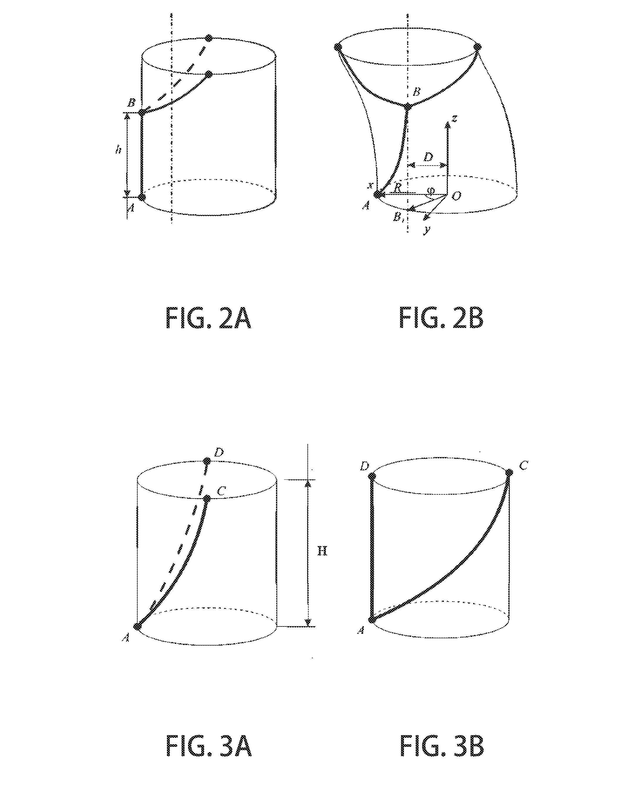

Image

  • Neck-wearable communication device with microphone array
  • Neck-wearable communication device with microphone array
  • Neck-wearable communication device with microphone array

Examples


Embodiment Construction

[0135]Reference will now be made in detail to the preferred embodiments of the present invention, examples of which are illustrated in the accompanying drawings.

[0136]In order to assure wearing a device on the user's body without additional support, it is expedient to provide the device in the form of a loop or a half-loop.

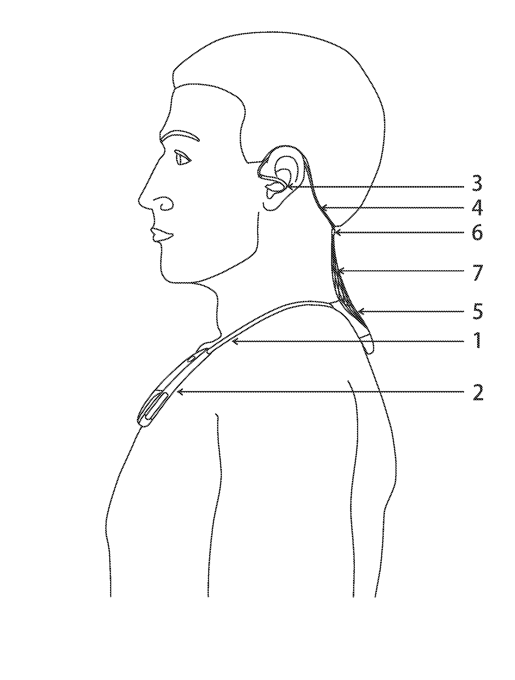
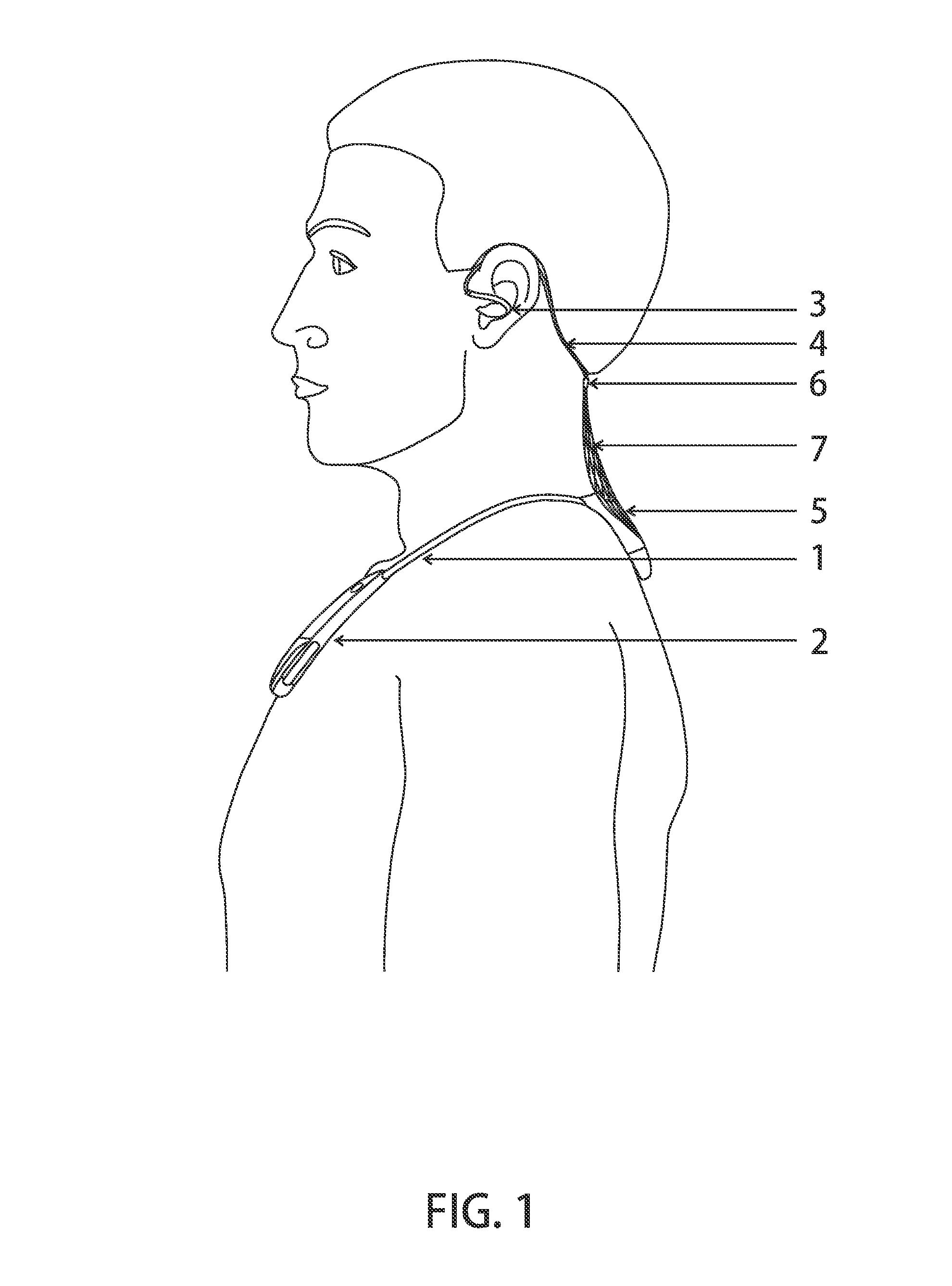
[0137]When a user wears a headset with neck-wearable housing having a generally U-shape (FIG. 1), a node that connects earphone cords 5 to a neck-wearable housing 1 rests on the dorsal surface of the user's neck, in the region of the seventh cervical vertebra. Slightly lower on the human body, there is a deepening trough, lying between the spinous and transverse processes of the vertebrae, sulcus dorsalis, at the level of the second—third thoracic vertebrae in the interscapular region, where a depression of various depth of about 4×5 cm (depending on the user's constitution and development of subcutaneous fat) is formed at the place of attachment on the medial edg...


PUM


Abstract

A wearable electronic device includes a neck-wearable housing, generally U-shaped, with an electrical connector; two in-ear earphones; two cords, with one end connected to one of the earphones and the other end connected to the connector. The two cords are mechanically connected to the housing. Points of connection of the cords to the housing are close to each other and form a dorsal node, and the two cords are mechanically connected to each other in their portions between the in-ear earphones and the dorsal node to form a suboccipital node. A microphone is placed in the housing on a front (chest) side of the user. A microphone is placed in the dorsal and / or in the suboccipital node. The microphones are used for determination of correlated and non-correlated components of audio signals. The correlated components are treated as a noise signal and the non-correlated components are a target signal.

Description

CROSS-REFERENCE TO RELATED APPLICATIONS[0001]This application is a continuation in part of U.S. patent application Ser. No. 15 / 052,240, filed on Feb. 24, 2016, which is a continuation of U.S. patent application Ser. No. 13 / 902,903, filed on May 27, 2013, which claims priority to Russian Patent Application No. 2012158157, filed on Dec. 28, 2012, all of which are incorporated herein by reference in their entirety.BACKGROUND OF THE INVENTION[0002]Field of the Invention[0003]The invention relates to telecommunication devices, and, more particularly, to a neck-wearable telecommunication device.[0004]Description of the Related Art[0005]Wearable telecommunication devices based on a necklace, collar, neckband, headband or other similar load-carrying structure are often used as an interface between a human being and a technical system, which may be a telecommunication system, a computer system, an entertainment system, a medical system, a security system, etc.[0006]Known stereo headsets in t...

Claims


Application Information

Patent Timeline
Patent Type & Authority Applications(United States)
IPC IPC(8): H04R1/10G10K11/178H04R1/40
CPCH04R1/1058H04R1/1033H04R1/105H04R1/406G10K2210/3046H04R1/1041G10K11/1786H04R2420/07G10K2210/3044H04R1/1016H04M1/05H04M1/15H04M1/6058H04R1/1066H04R1/1083H04R2201/023H04R2410/05
Inventor USHAKOV, ALEXEY LEONIDOVICH
Owner USHAKOV ALEXEY LEONIDOVICH
Learn More