
Machine Tool System and Method for Additive Manufacturing

a technology of machine tools and additive manufacturing, applied in the direction of manufacturing tools, metal-working equipment, welding equipment, etc., can solve the problems of requiring considerable investment in time, tools, effort, and additive process may generate “near-net shap

Inactive Publication Date: 2017-01-12
DMG MORI SEIKI ADVANCED SOLUTIONS
View PDF7 Cites 28 Cited by
  • Summary
  • Abstract
  • Description
  • Claims
  • Application Information

AI Technical Summary

Benefits of technology

The present patent describes a machine tool that can be used with a feed powder / propellant supply and a fabrication energy supply. The machine tool includes a first tool holder carrying a substrate, a second tool holder, and a processing head assembly coupled to the second tool holder. The processing head assembly has a feed powder / propellant interface, a fabrication energy interface, and a fabrication energy outlet. The machine control circuitry is operatively coupled to the first tool holder and the second tool holder. The machine control circuitry can position the tool holders to direct a fabrication energy beam onto the substrate to form an energy spot and to direct feed powder / propellant towards a powder target on the substrate. The machine tool can control the orientation of the second tool holder to maintain the offset distance between the beam target and the powder target as the energy spot moves across the substrate. The technical effects of this patent allow for a more precise and accurate fabrication process using a machine tool.

Problems solved by technology

To produce a complex assembly in final, usable form (“net shape”), a condition which requires not only the proper materials formed in the proper shapes, but also having the proper combination of metallurgical properties (e.g., various heat treatments, work hardening, complex microstructure), typically requires considerable investment in time, tools, and effort.
In some cases, however, the additive process may generate “near-net shape” products that require some degree of finishing.

Method used


Image

  • Machine Tool System and Method for Additive Manufacturing
  • Machine Tool System and Method for Additive Manufacturing
  • Machine Tool System and Method for Additive Manufacturing

Examples


Embodiment Construction

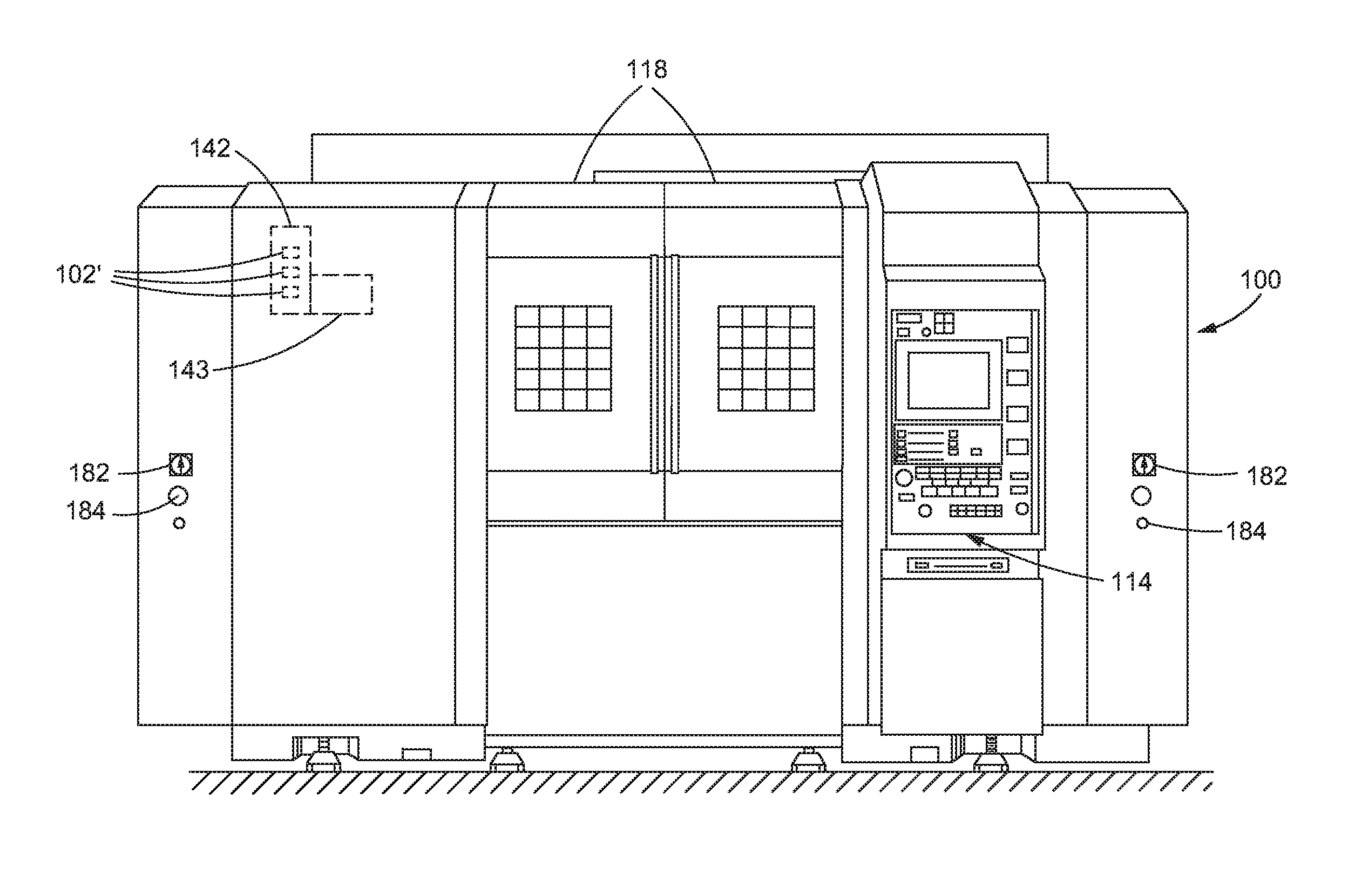
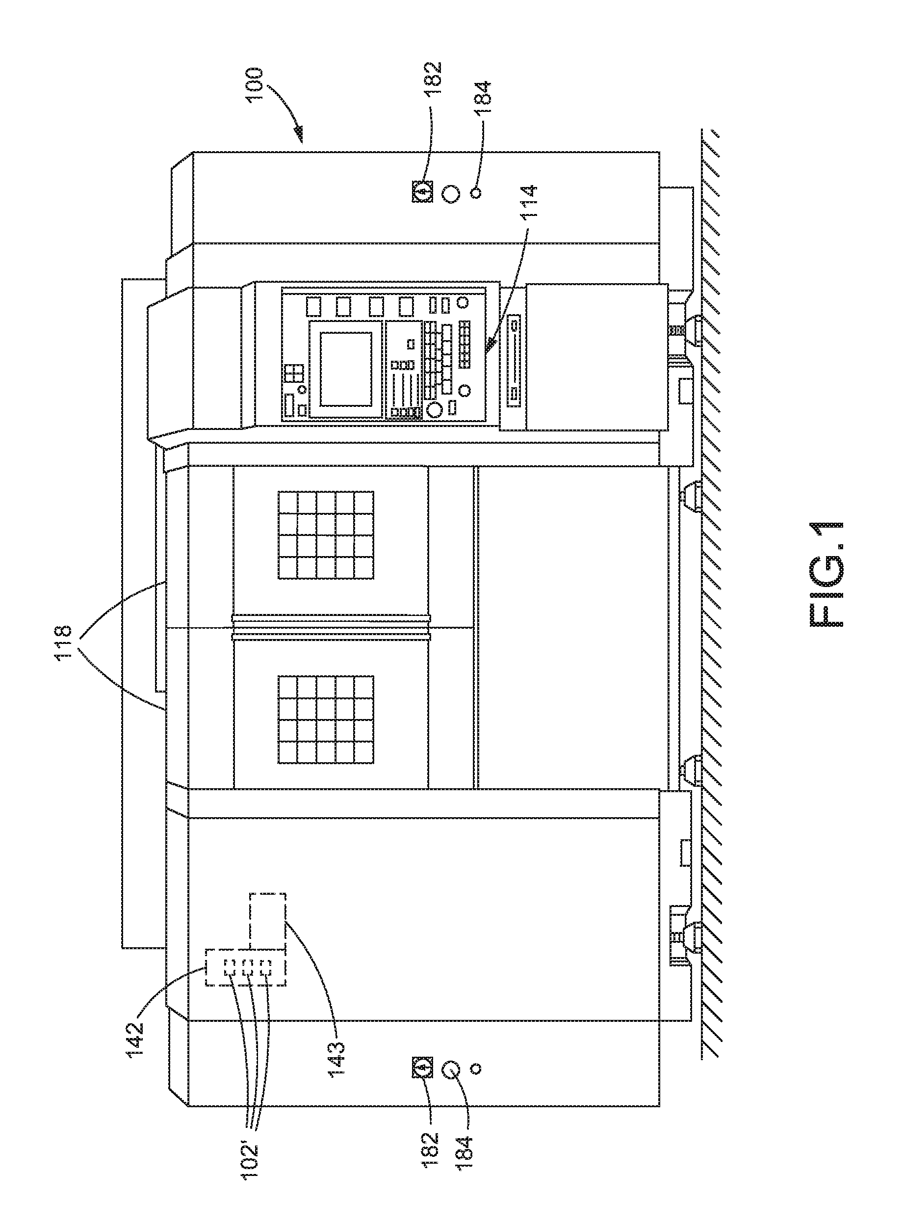
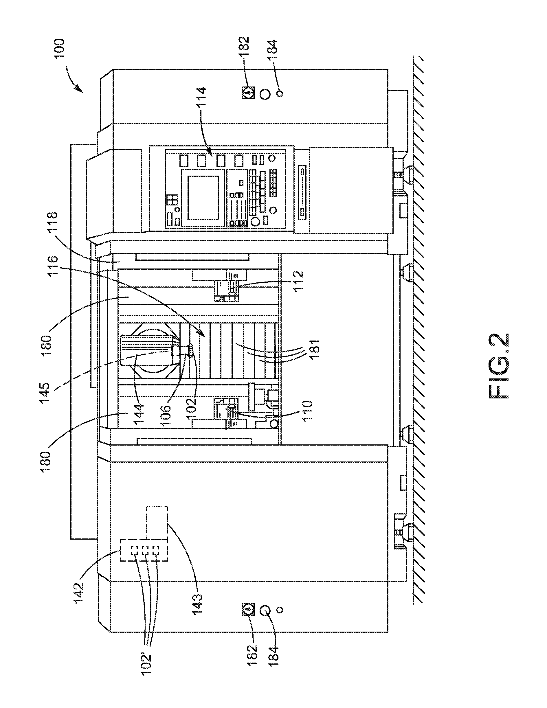
[0046]Any suitable apparatus may be employed in conjunction with the methods disclosed herein. In some embodiments, the methods are performed using a computer numerically controlled machine, illustrated generally in FIGS. 1-10. A computer numerically controlled machine is itself provided in other embodiments. The machine 100 illustrated in FIGS. 1-10 is an NT-series machine, versions of which are available from DMG / Mori Seiki USA, the assignee of the present application. Alternatively, DMG / Mori Seiki's DMU-65 (a five-axis, vertical machine tool) machine tool, or other machine tools having different orientations or numbers of axes, may be used in conjunction with the apparatus and methods disclosed herein.

[0047]In general, with reference to the NT-series machine illustrated in FIGS. 1-3, one suitable computer numerically controlled machine 100 has at least a first retainer and a second retainer, each of which may be a tool retainer (such as a spindle retainer associated with spindle ...


PUM

PropertyMeasurementUnit
spot angleaaaaaaaaaa
areaaaaaaaaaaa
spot angleaaaaaaaaaa

Abstract

Methods and apparatus for performing additive manufacturing processes using a machine tool may include controlling an orientation of a processing head to control the tangential angle of a fabrication energy beam, a feed powder nozzle, or both. The orientation of a non-circular energy beam may be control to more evenly distribute the energy beam across a width of a tool path. Additionally or alternatively, the orientation of the feed powder nozzle may be controlled to project toward a powder target that is spaced from a beam target. The powder target may be directed to a trailing edge of a beam spot formed by the energy beam to increase the amount of powder incorporated into a melt pool formed by the energy beam. Alternatively, the powder target may be directed to a leading edge of the beam spot to provide a self-correcting feature to address thickness errors formed in previous layers of added material.

Description

BACKGROUND[0001]Technical Field[0002]The present disclosure generally relates to computed numerically controlled machine tools, and more particularly, to methods and apparatus for performing additive manufacturing with machine tools.[0003]Description of the Related Art[0004]Traditionally, materials are processed into desired shapes and assemblies through a combination of rough fabrication techniques (e.g., casting, rolling, forging, extrusion, and stamping) and finish fabrication techniques (e.g., machining, welding, soldering, polishing). To produce a complex assembly in final, usable form (“net shape”), a condition which requires not only the proper materials formed in the proper shapes, but also having the proper combination of metallurgical properties (e.g., various heat treatments, work hardening, complex microstructure), typically requires considerable investment in time, tools, and effort.[0005]One or more of the rough and finish processes may be performed using Computer Nume...

Claims


Application Information

Patent Timeline
Patent Type & Authority Applications(United States)
IPC IPC(8): B23K26/342B23K26/08B23K26/144B23K26/073B33Y10/00B33Y30/00
CPCB23K26/342B33Y10/00B23K26/0869B23K26/144B23K26/073B33Y30/00B23K26/0732B23K26/0736B23K26/0853B23K26/0876B23K26/1482
Inventor HYATT, GREGORY A.CHAPHALKAR, NITINHRANKA, KARLPANZARELLA, MICHAEL J.
Owner DMG MORI SEIKI ADVANCED SOLUTIONS
Learn More