Yield Monitor for Windrow-Collected Materials
a technology of windrows and monitors, which is applied in the field of yield monitors for windrows, can solve the problems of limited commercial applications of precision agriculture technology for hay and forages, inability to accurately distribute hay across the field, and limited system us
- Summary
- Abstract
- Description
- Claims
- Application Information
AI Technical Summary
Benefits of technology
Problems solved by technology
Method used
Image
Examples
example 1
[0067]A boom was constructed from 2.5 cm (1 in.) square tubing and mounted to the tongue of a John Deere 458 hay baler. The boom was mounted to the bottom of the tongue so the tongue would not interfere with the sensors mounted to the boom.
[0068]On the boom, eight pieces of 5 cm×5 cm (2 in.×2 in.) angle iron were mounted in order to provide the sensors with a mounting point. Eight 3521_0 infrared distance sensors (Phidgets Inc., Calgary, Alberta, Canada) were mounted to the angle iron. Each of the sensors was equally spaced along the 99 cm (39 in.) boom. Four Model 1128_0 ultrasonic sensors (Phidgets Inc., Calgary, Alberta, Canada) were secured to every other of piece of the angle iron.
[0069]A model LJC18A3 B Z / AX capacitance-based proximity switch was mounted at the hub of the baler. This switch sensed each of the wheel studs as they passed by, signaling for a sensor reading to be logged.
[0070]The ultrasonic and infrared distance sensors that were mounted to the boom were connected...
example 2
[0103]The Phidgets ultrasonic sensors described above in Example 1 were replaced by Maxbotix 7060, Maxbotix 7067 (MaxBotix Inc., Brainerd, Minn.), and model T30UXDA ultrasonic sensors (Banner Engineering Inc., Minneapolis, Minn.). The 7060 sensors demonstrated problems. The T30UXDA sensors consistently responded proportionately with the target distance regardless of whether or not the sensor platform was in forward motion and demonstrated a higher level of resolution because the sensors were designed for a 1 meter distance range, therefore utilizing almost all of the window of sight between the baler tongue and ground.
[0104]A data acquisition program display is provided in FIG. 8; the need for tagging hay bales was eliminated to reduce labor required for data collection and to reduce opportunities for human error. To accomplish this, the hay yield monitoring program was modified to record the GPS coordinates (latitude, longitude) of where each bale was ejected. A GPS offset opposite...
example 3
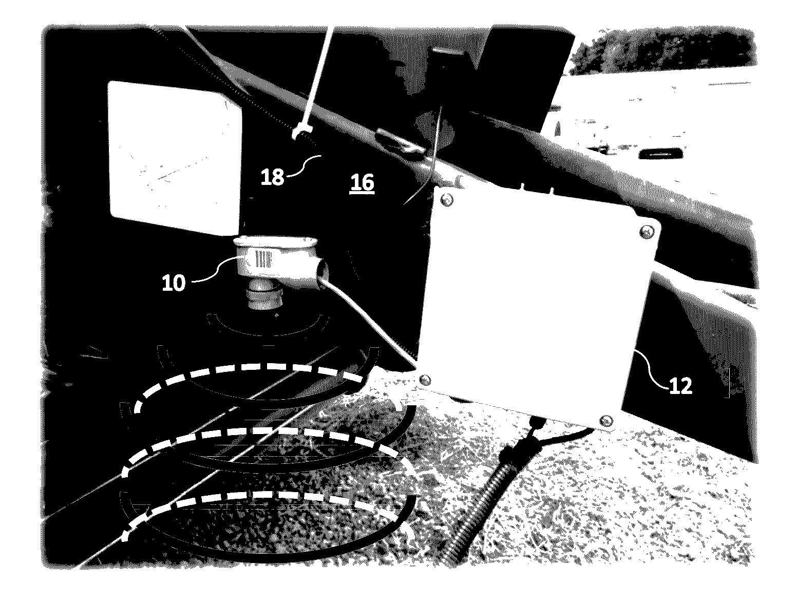
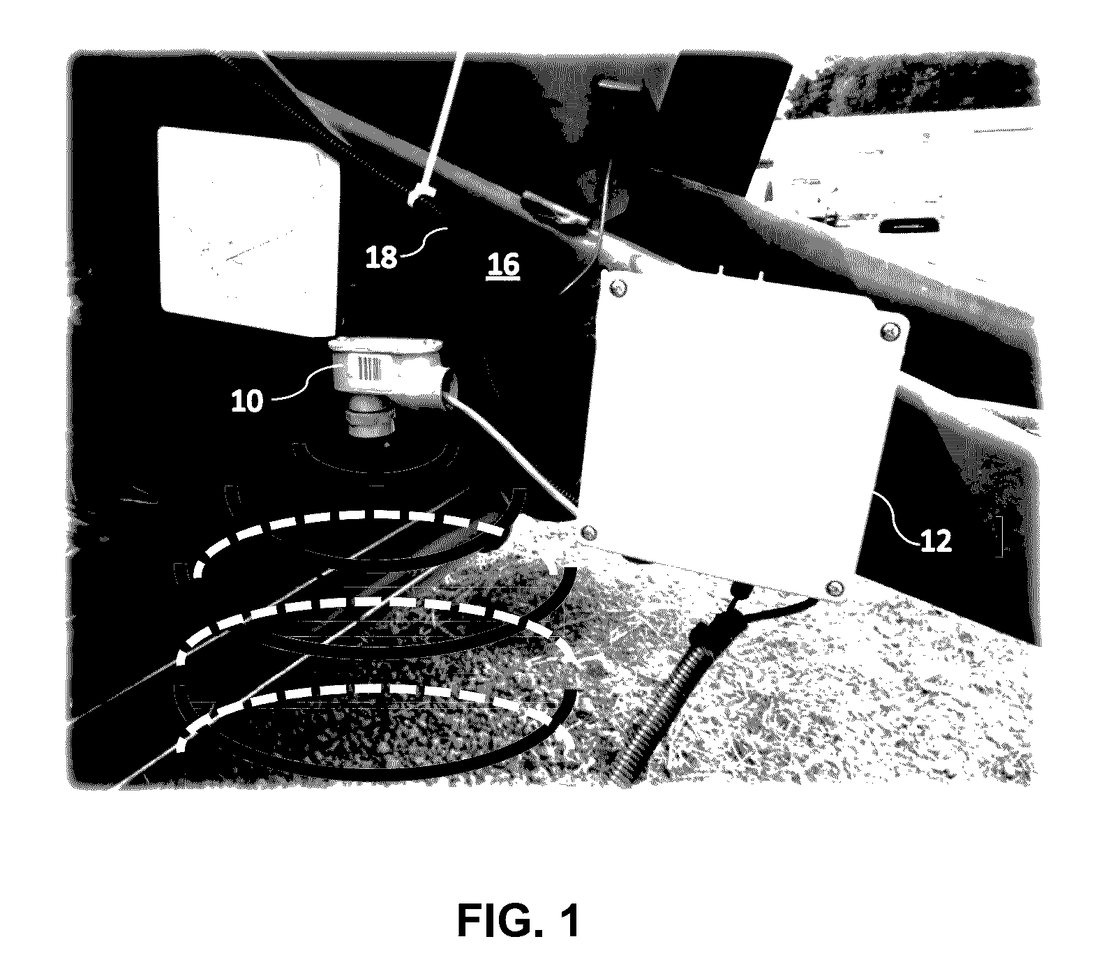
[0117]A system was installed on two round balers: a New Holland Roll Belt Model 450 Silage Special and a John Deere Model 459 Silage Special. Both systems utilized a pair of Banner Engineering Model T30UXDA ultrasonic sensors mounted at each side of the baler tongue near the windrow pickup as shown in FIG. 14. This system eliminated the capacitance travel distance switches utilized in Example 2 and modified the mass flow prediction algorithm to support their absence.
[0118]Voltage dividers were provided for the 0-10V return ultrasonic sensors to accommodate a 5V analog input controller. A John Deere model AH116104 shaft speed sensor was installed on each baler to indicate PTO shaft speed (FIG. 15) and both balers were equipped with sub-meter accuracy GPS units. The components from each system were wired into a programmable controller, which transmitted to mass flow data to a commercially available yield monitoring display.
[0119]A Boolean “IsHarvesting?” variable was updated continuou...
PUM
 Abstract
Description
Claims
Application Information
 - R&D
- Intellectual Property
- Life Sciences
- Materials
- Tech Scout
- Unparalleled Data Quality
- Higher Quality Content
- 60% Fewer Hallucinations
Browse by: Latest US Patents, China's latest patents, Technical Efficacy Thesaurus, Application Domain, Technology Topic, Popular Technical Reports.
© 2025 PatSnap. All rights reserved.Legal|Privacy policy|Modern Slavery Act Transparency Statement|Sitemap|About US| Contact US: help@patsnap.com


